
Electric fence control circuit 5

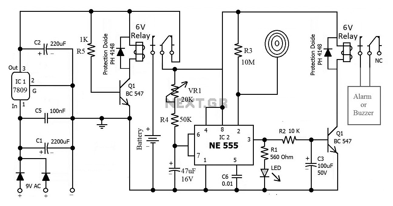
The electric fence control circuit operates by utilizing a +6 V power supply to facilitate the functioning of its various components. The power control button (S) serves as the primary switch, allowing the operator to turn the system on or off. The power transformer (T) steps down the voltage from the main supply to the required level, ensuring safe operation of the circuit.
Rectifier diodes (VD8-VD11) are employed to convert the alternating current (AC) output from the transformer into direct current (DC), which is essential for powering the circuit. The filter capacitor (C5) smooths out any ripples in the DC output, providing a stable voltage to the subsequent circuits.
The high-voltage output circuit generates the necessary voltage to create an electric charge along the fence line, deterring intruders. The trigger control circuit monitors the fence's integrity, activating the high-voltage output when a breach is detected. The alarm circuit provides audible or visual signals to alert the property owner of any unauthorized access attempts.
Finally, the protection circuit safeguards the entire system from overcurrent and voltage spikes, ensuring reliability and longevity of the electric fence control circuit. This comprehensive design ensures effective operation, safety, and ease of use for electric fencing applications.The electric fence control circuit is composed of the +6 V power supply circuit, high-voltage output circuit, trigger control circuit, alarm circuit and protection circuit, and it is shown in Figure 4-30. +6 V power supply circuit is composed of the power control button S, power transformer T, rectifier diodes VD8-VDll, filter capacitor C5, current-limiting..
🔗 External reference
Related Circuits
This bulletin outlines the applications, design features, equipment arrangement, and space planning for the type 230 controllers. These controllers are designed for the control and protection of induction motors or transformers in 2300-4160 volt systems. Each type 230 controller...
This is the circuit diagram of a touch-activated alarm system that remains operational during power outages. The alarm system is triggered when someone touches the designated touch plate. A notable feature of this circuit is the automatic battery activator,...
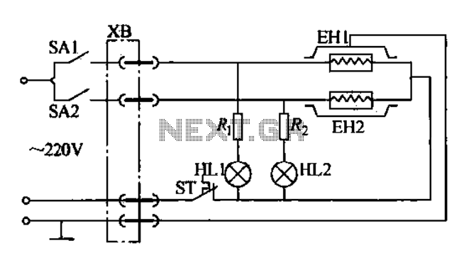
Currently, the use of cookers has become fashionable due to their speed, cleanliness, and low pollution levels, making them a favorite among consumers. Cookers circuit. The modern cooker circuit typically involves a combination of heating elements, control systems, and safety...
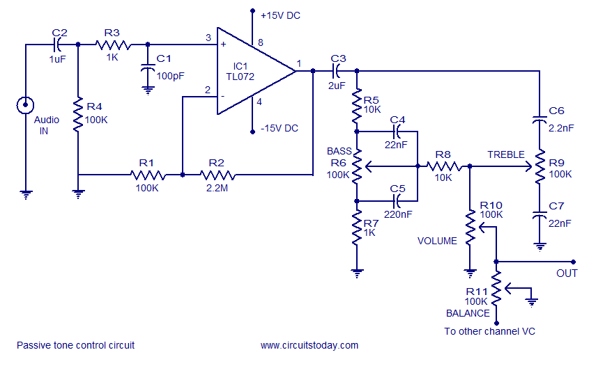
Tone control circuit utilizing an operational amplifier and a Baxandall passive tone control configuration. The overall gain is 25 dB, with a boost and cut capability of 20 dB. The circuit is powered by a dual 15V supply. The tone...
The input impedance of AC-coupled operational amplifier (op-amp) circuits is primarily determined by the resistance that establishes the DC operating point. When using CMOS op-amps, the input impedance is high, reaching up to 10 MΩ in current op-amps. For...

This design outlines a sensor circuit that utilizes an LED as a light sensor. The operational control and amplification of the output are managed by a 1458 integrated circuit (IC), which functions as an operational amplifier (op-amp). The circuit...