
Infrared Remote Control for operates on 115 volts AC

The infrared remote control circuit designed for operation at 115 volts AC utilizes a transmitter and a receiver to control various electrical devices. The transmitter typically incorporates an infrared LED that emits modulated infrared signals. These signals are generated by a microcontroller or a simple oscillator circuit, which encodes commands corresponding to different functions, such as turning devices on or off.
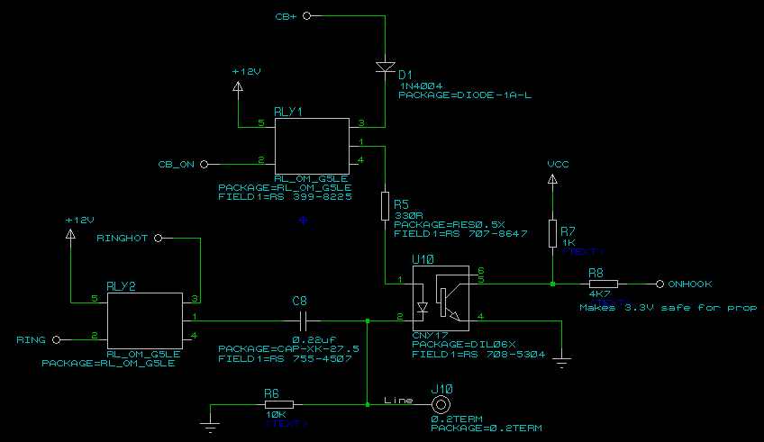
The receiver circuit, based on the Radio Shack infrared module, is equipped with a photodiode or phototransistor that detects the infrared signals. Upon receiving a signal, the receiver outputs a corresponding voltage level that can be used to control a relay or a triac. This output effectively acts as a switch for the connected load, allowing the user to control high voltage AC devices safely.
The relay or triac in this circuit is crucial as it provides electrical isolation between the low-voltage control circuit and the high-voltage AC load. When the receiver detects an infrared command, it activates the relay, closing the circuit and allowing current to flow to the connected device. The relay should be rated appropriately for the load it will control, ensuring safe operation without risk of failure.
To enhance the circuit's robustness, it is advisable to include protection components such as diodes across the relay coil to prevent back EMF from damaging the control circuitry. Additionally, integrating a fuse in the AC line can protect against overcurrent situations.
For optimal performance, the infrared remote control should be tested in various conditions to ensure reliable operation across different distances and angles. Adjustments to the modulation frequency and the receiver sensitivity may be necessary to improve the overall functionality of the system.Infrared Remote Control for operates on 115 volts AC. This circuit will allow you to turn on any piece of equipment that operates on 115 volts ac. The receiver circuit is based on the Radio Shack infrared. 🔗 External reference
Related Circuits
Here is a simple project that sends continuous or switch controller MIDI messages that correspond to the position of a potentiometer. Given a few parts and a cannibalized volume or wah-wah pedal, you can build this MIDI controller pedal...
A four-channel DMX512 controlled ringer. The Mk 3 will also incorporate a ringing supply generator, making it reproducible by those without access to the BT ringing supply Number 7. The ringer is microprocessor-controlled, utilizing a Parallax Propeller-based chip, specifically...

The circuit illustrated in Figure 1 generates a precise variable-frequency sine wave intended for use as a general-purpose reference signal. It incorporates an 8th-order elliptic switched-capacitor low-pass filter (IC3), which is clocked by a 100 kHz square wave produced...
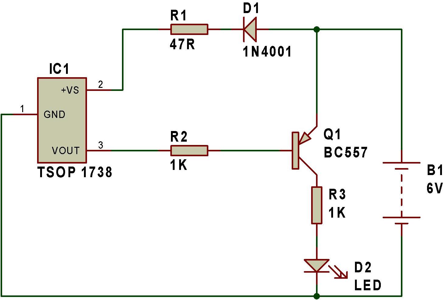
The remote tester circuit operates similarly to a dark sensor using a BC557 transistor. An LDR has been substituted with an IR sensor, specifically the TSOP 1738. The circuit functions as a remote tester; when a remote control switch...
Most, if not all, recent cars have a significant amount of electronics, including ABS brake systems, engine control with injection calculators, and airbags. Modern automobiles are equipped with a wide array of electronic systems that enhance performance, safety, and comfort....
The article on the RGB LED fader has been one of the most visited articles on this blog. Since its publication, another microcontroller-based RGB LED project has been designed and built, this time controlling the colors from a computer...