
remote tester

The remote tester circuit is designed to detect infrared signals emitted by remote controls, utilizing the TSOP 1738 IR receiver module. This component is sensitive to the modulated infrared light typically emitted by remote control devices, allowing it to effectively capture signals. The BC557 transistor serves as a switch in the circuit, enabling the LED D2 to illuminate when an infrared signal is detected.
In operation, when the remote control is pointed towards the IR sensor and a button is pressed, the TSOP 1738 receives the signal. This signal is processed by the circuit, activating the BC557 transistor, which in turn allows current to flow through the LED D2, causing it to light up. This visual indication confirms that the remote control is functioning and that the signal is being transmitted successfully.
The circuit can be powered using a standard power supply, and the component values can be adjusted based on the desired sensitivity and response time. For instance, the use of capacitors and resistors in conjunction with the TSOP 1738 can filter out noise and improve the reliability of the signal detection.
This remote tester circuit is compact and can be integrated into various applications where remote control functionality needs to be verified, making it a valuable tool for electronics enthusiasts and professionals alike.Remote tester circuit also resembles the logic of a dark sensor (using BC557) . LDR has been replaced with IR sensor TSOP 1738. The circuit works as a remote tester. Pressing a remote control switch near the IR sensor, switches on the LED D2. I am Sagar Sapkota living in Espoo, Finland. I have done Master`s degree in Electronics and Communicatio ns with major in Electronics Productization from the University of Turku, Finland. I love to share my electronics works with the world. You can buy my kits at buildcircuit. org. - Sagar Sapkota 🔗 External reference
Related Circuits
A good/bad transistor tester is an instrument designed to determine the operational status of a transistor, indicating whether it is functional or defective. This device provides a simple binary assessment, confirming if the transistor has a gain equal to...
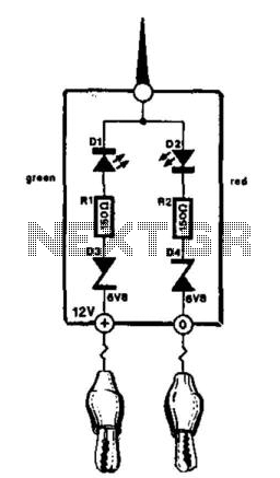
This compact tester is designed for checking vehicle electrical circuits. Two LEDs indicate whether one of the clips is connected to the positive supply line (red) or to ground (green). The unit is powered by the vehicle battery. It...
.jpg)
The project outlines a method to add a cost-effective remote doorbell to an existing household doorbell system, particularly useful for individuals who may not hear the doorbell when in the basement. The household doorbell operates on a continuous 24VAC...
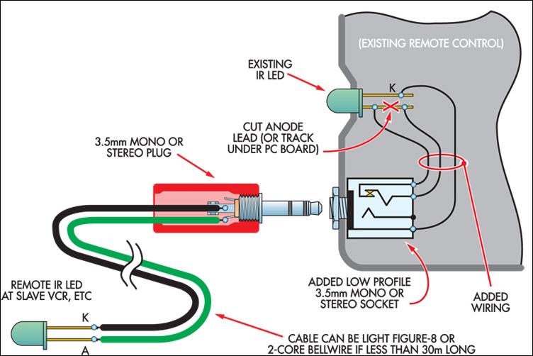
This ultra-simple remote control extender is ideal for use with a hidden video recorder. The recorder is a Panasonic NV-SD200 and is employed as part of a camera surveillance system. A PICAXE-08-based circuit detects events and controls the recorder....
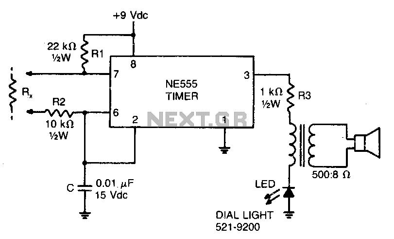
This low-current audio continuity tester indicates the unknown resistance value by the frequency of the audio tone. A high tone indicates a low resistance, while a tone of a few pulses per second indicates a resistance as high as...
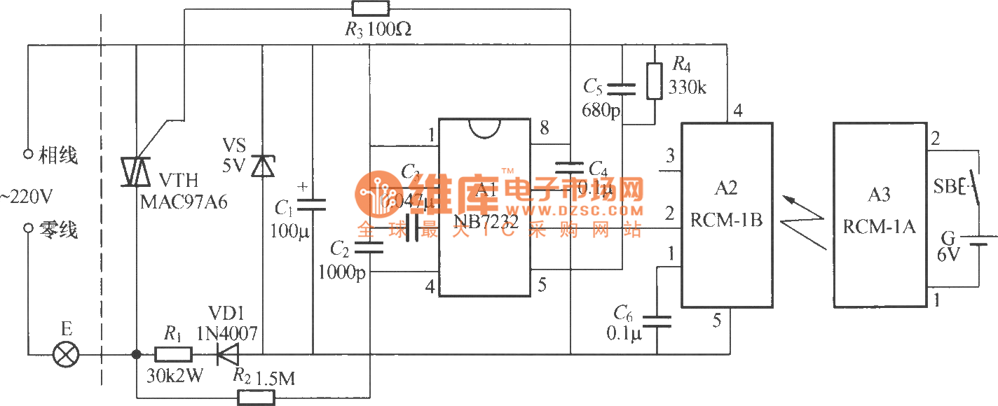
The diagram above illustrates a radio remote control dimmer circuit. This circuit utilizes a micro radio transmit/receive module in conjunction with a light modulation ASIC, resulting in a compact and easily producible design. It operates reliably and features a...