
MIDI Controller Footpedal
The MIDI controller pedal described serves as an interface for musicians to manipulate MIDI data in real-time, translating the physical position of a potentiometer into MIDI control changes. The circuit typically consists of a potentiometer, microcontroller, MIDI interface, and a panic button.
The potentiometer acts as an analog input device, translating the user's foot movement into a variable resistance that is read by the microcontroller. The microcontroller, programmed to interpret the potentiometer's output, converts the varying voltage levels into corresponding MIDI messages. These messages can be continuous controller messages (CC) or switch messages, depending on the configuration of the potentiometer and the desired output.
To construct the MIDI controller pedal, the following components are necessary:
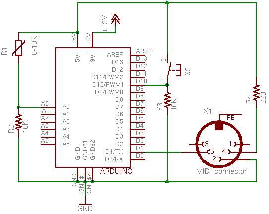
1. **Potentiometer**: A linear or logarithmic potentiometer (typically 10kΩ to 100kΩ) is used to control the MIDI data. The choice of potentiometer affects the response curve of the pedal.
2. **Microcontroller**: A suitable microcontroller, such as an Arduino or a dedicated MIDI controller chip, is used to process the analog signals from the potentiometer and output MIDI messages via a serial interface.
3. **MIDI Interface**: This can be a standard 5-pin DIN connector or a USB output, allowing the pedal to connect to other MIDI-capable devices.
4. **Panic Button**: A momentary push button connected to the microcontroller that, when pressed, sends a MIDI "All Notes Off" message to silence any notes that may be stuck due to transmission errors or other issues.
The circuit design should include power supply considerations, typically using a 9V battery or an external power adapter. Proper grounding and shielding techniques should be employed to minimize noise and interference, especially in live performance settings.
The enclosure for the pedal can be constructed from durable materials to withstand foot traffic, and the layout should allow for easy access to the panic button and potentiometer while ensuring stability during use.
In summary, this MIDI controller pedal provides musicians with a versatile tool for real-time MIDI manipulation, enhancing live performances and studio sessions alike. The incorporation of a panic button adds a layer of reliability, ensuring that performers can quickly address any issues with stuck notes.Here`s a simple project that sends continuous or switch controller MIDI messages that correspond to the position of a potentiometer. Given a few parts and a cannibalized volume or wah-wah pedal, you can build this MIDI controller pedal and have the ultimate source of controller data in the Universe.
This pedal is especially useful in live performance, but it`s also great to have around when sequencing. An added bonus: the MIDI Footpedal sports a panic button that will silence any stuck notes that come your way.
🔗 External reference
Related Circuits
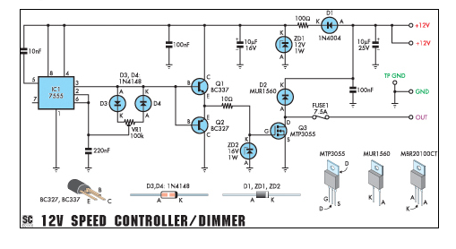
This circuit can function as a speed controller for a 12V motor with a continuous rating of up to 5A or as a dimmer for a 12V halogen or standard incandescent light. The circuit utilizes a pulse-width modulation (PWM) technique...
This page covers only the details of MIDI communication on the Arduino module. For a more general introduction to MIDI on a microprocessor, see the MIDI notes on Tom's physical computing site. MIDI, the Musical Instrument Digital Interface, is...
Understanding how to program the PIC microcontroller in theory is beneficial; however, practical learning occurs when the code is executed on a PIC within a circuit. One can either construct a new circuit for each test or utilize a...
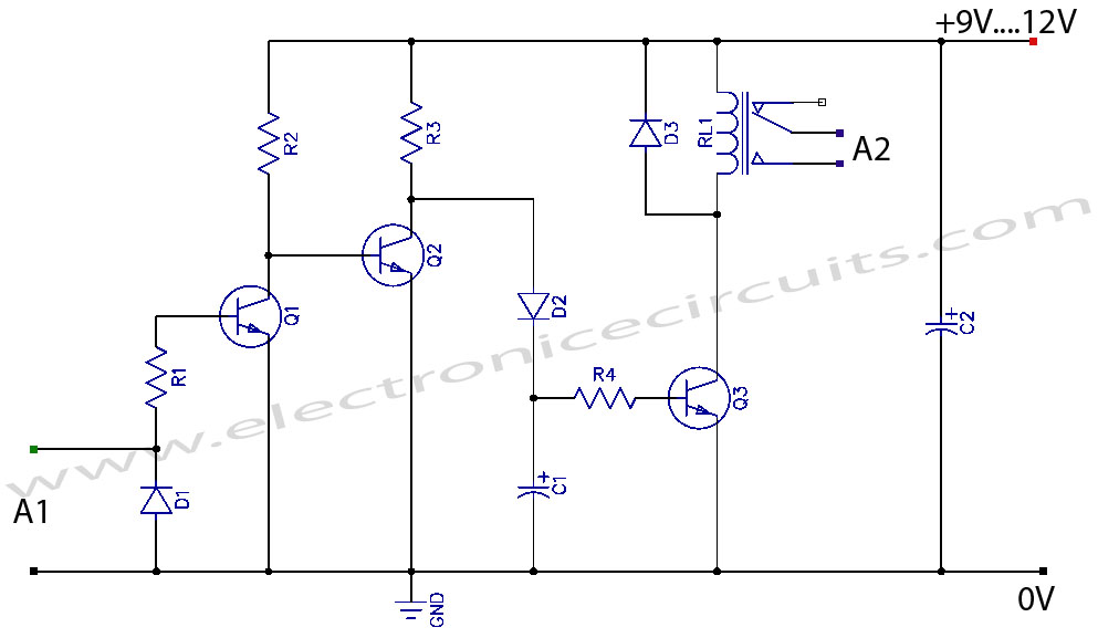
No description available. More: Q1, Q2: Standard-Transistoren D1: SB130 Q3: RFD 15 N 05 IC1A: CD4011B (if SMD) IC1B: detto The provided components suggest a basic electronic circuit that incorporates both transistors and integrated circuits, along with a diode. The circuit...
The 8051 microcontroller features a transmit channel and a receive channel for serial communication. The transmit data pin (TXD) is designated as P3.1, while the receive data pin (RXD) is located at P3.0. The serial signals on these pins...
VCR Camera Video Detector Switch Controller Circuit. This video detector switch controller circuit utilizes the video output from a VCR or camera to... This circuit functions as a video detector switch controller, designed to manage the video output from a...
Warning: include(partials/cookie-banner.php): Failed to open stream: Permission denied in /var/www/html/nextgr/view-circuit.php on line 713
Warning: include(): Failed opening 'partials/cookie-banner.php' for inclusion (include_path='.:/usr/share/php') in /var/www/html/nextgr/view-circuit.php on line 713