
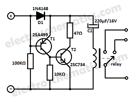
Infrared remote control relay circuit b
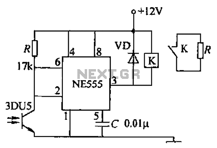
The circuit consists of two main components: the transmitting part, which includes an infrared light-emitting diode (LED), and the receiving part, which incorporates a phototransistor (3DU5) to detect the emitted infrared light. The LED is powered by a suitable voltage source, and it emits infrared light that can be detected by the phototransistor.
When the infrared light emitted by the LED strikes the phototransistor, it generates a corresponding electrical signal. This signal is then routed to terminal 3 of the NE555 timer. The NE555 timer is configured in monostable mode, meaning it will produce a single output pulse in response to the input signal from the phototransistor. The duration of this pulse can be adjusted by changing the resistor and capacitor values connected to the timer.
The output from the NE555 timer is used to energize a relay coil. When the timer output goes high, it activates the relay, pulling in its normally open contacts. This allows current to flow through the load connected to the relay, thus enabling it to operate. The relay acts as a switch that can control higher power devices, making this circuit suitable for various applications, such as remote control systems or automation tasks.
Overall, this circuit effectively demonstrates the principles of infrared communication and relay control, providing a practical solution for wireless signal transmission and device activation. Proper component selection and circuit design ensure reliable operation and responsiveness to the emitted infrared signals.A transmitting circuit, power, infrared light-emitting diode emits light receiving circuit shown in Figure, receives infrared light transistor 3DU5, the received signal output terminal 3 through NE555 timer, relay coil has electrical pull its normally open contact group together, so that the work load.
Related Circuits
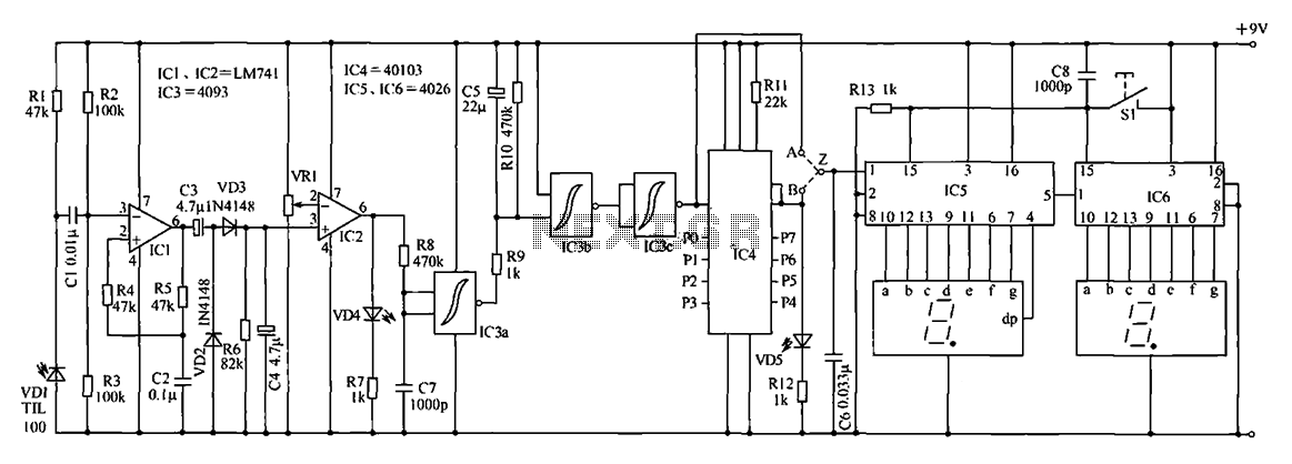
This timer is designed for individuals seeking to achieve a tan while minimizing excessive exposure to sunlight. A rotary switch allows the user to set the timer based on six classified photo-types. A photoresistor adjusts the preset time value...
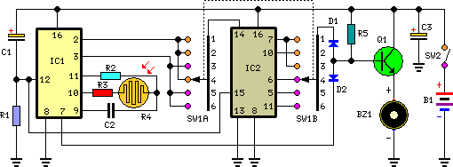
The digital counter circuit described utilizes an infrared signal to detect moving targets, making it suitable for counting small devices on a production line as they move along a conveyor belt. This circuit can also be employed for various...
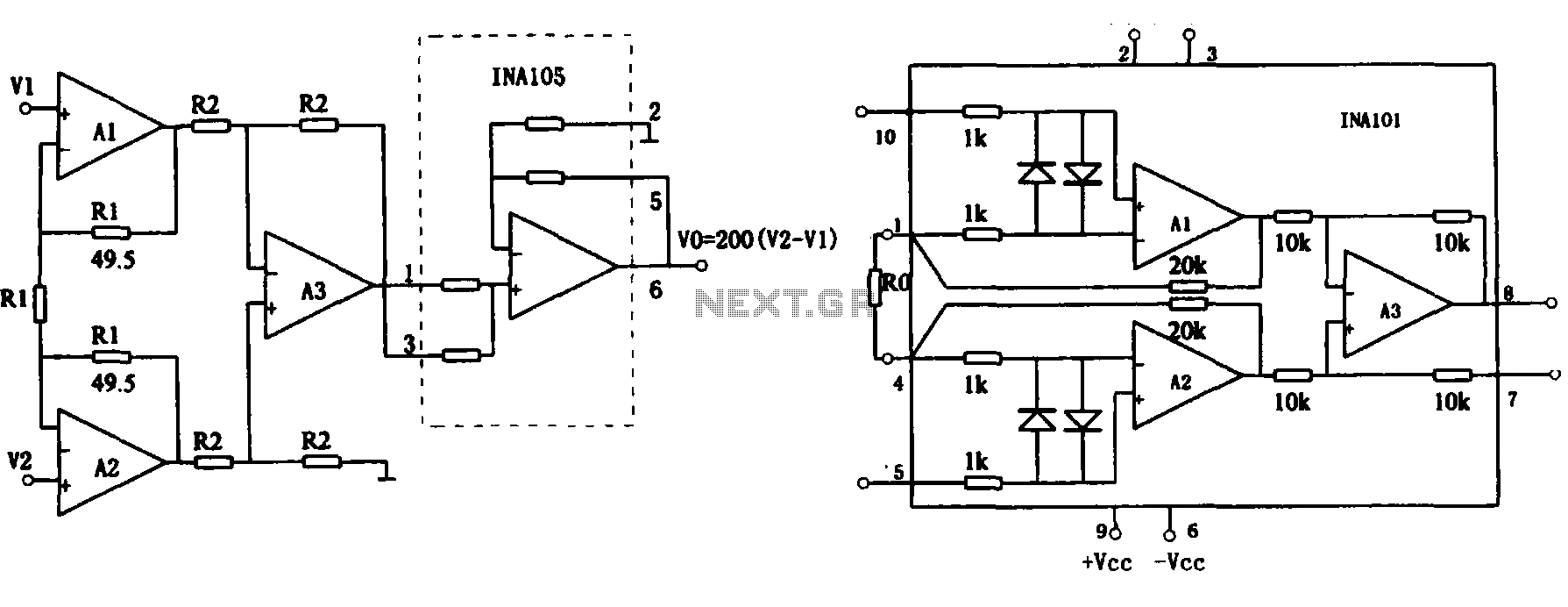
This document describes the extended common mode input voltage range of an instrument amplifier circuit. The circuit consists of three precision instrument amplifiers, A1, A2, and A3, which can be INA101 or INA102 models. The figure illustrates that A1,...
Protect your equipment with this compact 12V time delay relay circuit. The SMPS-based power supply of modern electronic devices is susceptible to voltage spikes. This 12V time delay relay circuit is designed to safeguard sensitive electronic devices by providing a...
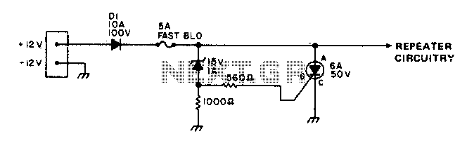
To protect portable emergency power repeaters from reverse or excessive voltage, diode D1 prevents damage from incorrect polarity, while the zener diode voltage sets the maximum voltage that can reach the rest of the circuitry. Additionally, a fast-blowing fuse...
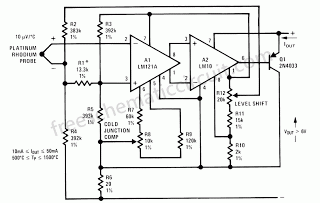
This circuit demonstrates how a low-drift preamplifier can enhance the measurement resolution of a thermocouple. The preamplifier is powered by the reference regulator, and bridge feedback is employed to bias the preamplifier input within its common mode range. Cold...
Warning: include(partials/cookie-banner.php): Failed to open stream: Permission denied in /var/www/html/nextgr/view-circuit.php on line 713
Warning: include(): Failed opening 'partials/cookie-banner.php' for inclusion (include_path='.:/usr/share/php') in /var/www/html/nextgr/view-circuit.php on line 713