
Transmitter Precision Thermocouple Amplifier Circuit
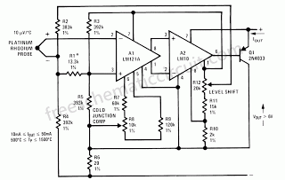
The described circuit is centered around enhancing the performance of thermocouples by integrating a low-drift preamplifier. The preamplifier's role is critical in improving the signal-to-noise ratio, thus allowing for more accurate temperature measurements. The use of a reference regulator to power the preamplifier ensures stable operation, which is essential for precision applications. The bridge feedback mechanism serves to maintain the input of the preamplifier within its common mode range, thereby minimizing the risk of distortion in the signal.
Cold junction compensation is a crucial aspect of thermocouple measurements, as it corrects for the temperature at the connection point between the thermocouple and the measurement device. By setting the offset voltage into amplifier A1, the circuit can effectively adjust for variations in ambient temperature, ensuring that the readings reflect only the temperature being measured.
The specified drift of 0.2 µV/°C for the preamplifier indicates a high level of stability, which is essential for applications requiring precise temperature control. The drift components associated with the reference and the bridged configuration further highlight the importance of maintaining low drift characteristics throughout the circuit.
Adjustments to the preamplifier gain can be made by modifying the resistance values of R7 and R9. However, this necessitates careful consideration of the output voltage from the reference regulator, as increasing the gain will also raise the minimum terminal voltage required for optimal performance. The design accommodates operation at lower voltages, which is beneficial for power-sensitive applications, although it may require additional testing to ensure reliability and performance under these conditions.
In summary, this circuit exemplifies a sophisticated approach to thermocouple measurement, utilizing a low-drift preamplifier, effective cold junction compensation, and careful design considerations to achieve high measurement accuracy and stability.This circuit is shows how a low drift preamplifier can be added to improve the measurement resolution of a thermocouple. The preamp is powered from the reference regulator, and bridge feedback is used to bias the preamp input within its common mode range.
Cold junction compensation is provided with the offset voltage set into A1, it being directly proportional to absolute temperature. The maximum drift specification for the preamp is 0. 2 µV/ °C. For this particular circuit, an equal drift component would result for 0. 004%/ °C on the reference, 0. 001%/ °C mismatch on the bridged The op amp drift might be desensitized by raising the preamp gain (lowering R7 R9), but this would require raising the output voltage of the reference regulator and the minimum terminal voltage. In this application, the preamp is run at a lower voltage than standard parts are tested with, and the maximum supply current specified is high.
However, there should be no problem with the voltage; and a lower, maximum supply current can be expected at the lower voltage. Even so, some testing may be in order. 🔗 External reference
Related Circuits
741 Stereo PreAmplifier Circuit Diagram. This preamp circuit provides better than 20dB gain in each channel. PARTS LIST R1 -.. The 741 stereo preamplifier circuit is designed to amplify audio signals with a gain of over 20 dB in each...
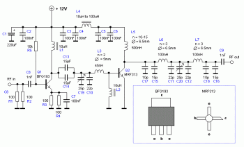
An RF power amplifier is a type of electronic amplifier used to convert a low-power radio-frequency signal into a larger signal of significant power, typically for driving the antenna of a transmitter. It is optimized for high efficiency, high...
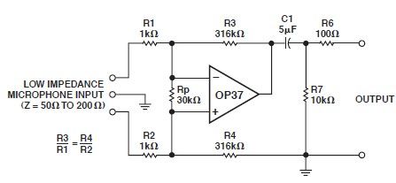
This microphone preamp schematic is an electronic circuit project utilizing the OP37 operational amplifier from Analog Devices. It functions as a fixed-gain transformerless microphone preamp, amplifying differential signals from low-impedance microphones by 50 dB, with an input impedance of...
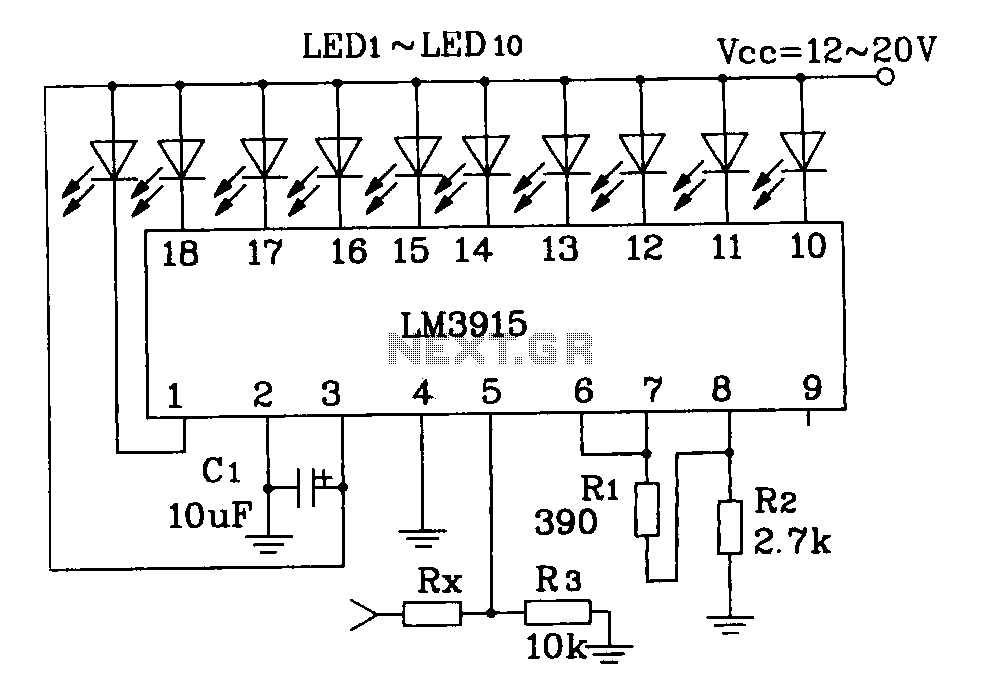
This document describes a simple LM3915 audio power meter circuit diagram. It notes that if the internal resistance of the speaker is 4 ohms, a resistor value of 10k ohms should be used for Rx. For an 8-ohm speaker,...
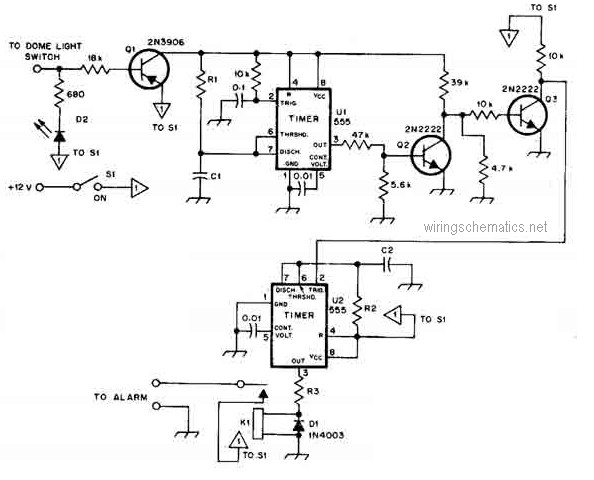
This circuit diagram represents a smart car alarm timer. This design is more advanced compared to traditional car alarm systems. When activated, the alarm remains active for 80 seconds, following an initial delay of 15 seconds. The smart car alarm...
A two-tone generator that is alternately switched ON provides a high/low output similar to that of a traffic vehicle, such as a police car or ambulance. The CD4011 integrated circuit (IC1), which is a quad 2-input NAND gate, functions...