
InfraRed Remote Switch

This remote-controlled switchboard project utilizes an AT89C52 microcontroller as the core processing unit, which is an 8-bit microcontroller from the 8051 family. The microcontroller is responsible for interpreting the infrared (IR) signals received from a standard remote control. The system can manage up to six electrical devices, each being controlled through individual relays. The relays act as switches that can handle a maximum load current of 5 Amperes, enabling the control of standard home appliances.
The infrared receiver module is connected to the microcontroller, allowing it to detect and decode the signals transmitted by the remote control. Each button on the remote corresponds to a specific command that the microcontroller interprets to switch the relays on or off. This feature allows users to control multiple appliances from a distance of up to 10 meters, providing convenience and flexibility in managing home devices.
To ensure reliability and maintain the state of the devices even after power loss, the system incorporates an EEPROM (Electrically Erasable Programmable Read-Only Memory) IC. This component stores the operational conditions of the devices, ensuring that the last state of each appliance is remembered and restored upon reactivation of the system.
For applications requiring higher power loads, the circuit can be modified by replacing the relays with higher-rated ones, thereby accommodating devices that exceed the standard 5 Ampere limit. The design of the circuit involves careful consideration of the power ratings and specifications of all components to ensure safe and efficient operation.
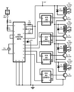
In summary, this remote-controlled switchboard project exemplifies a practical application of microcontroller technology in home automation, offering a user-friendly interface for controlling multiple devices with ease. The integration of EEPROM for state retention and the flexibility of relay configuration further enhance the functionality and adaptability of the system in various household settings.This Project REMOTE CONTROLLED SWITCH BOARD is used to switch on/off the Home Appliances by using a standard Remote control. The system is used to switch on/off upto six electrical devices. All the above processes are controlled by the 8 bit Microcontroller AT89C52. The Microcontroller receives the Infrared Signal from the receiver and it decodes and switch on/off the appropriate Device.
The Range of the system is unto 10 meters. The project can switch on/off electrical devices of maximum load current of 5Amperes. High power loads can also be connected by changing the Relay. The conditions of the devices are stored in the EEPROM IC. And t 🔗 External reference
Related Circuits
This article provides insights on how to interface infrared (IR) remote controllers with a computer. Possible applications include controlling a computer using a TV remote or managing a VCR through a computer. The circuit discussed was initially shared in...
Envision a scenario where one is comfortably reading a favorite novel while enjoying music on a computer. Suddenly, the desire arises to skip the current song or pause the MP3 player. An infrared software solution is available that decodes...
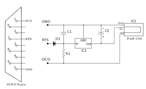
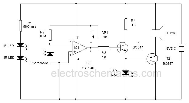
This type of infrared proximity circuit is commonly utilized as an electric switch where physical contact is undesirable for hygiene reasons. For instance, infrared proximity sensors are frequently found in public drinking fountains and washrooms. The straightforward circuit described...
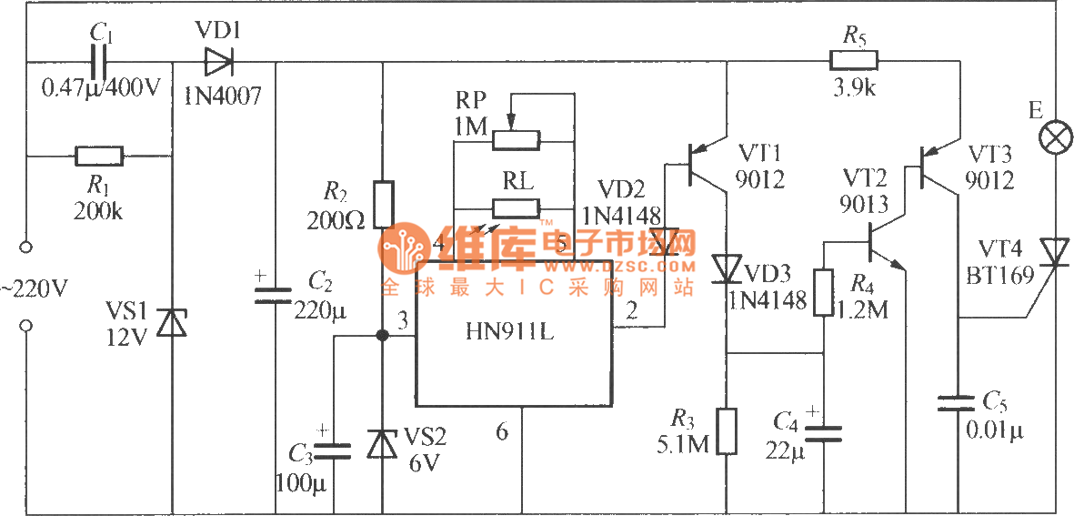
The figure illustrates an automatic light sensing system utilizing the HN911L pyroelectric infrared detection module. The HN911L incorporates high-sensitivity infrared sensors, a passive infrared (PIR) sensor, amplifiers, a signal processing circuit, and an output circuit. This module is capable...
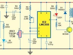
This infrared alarm barrier is designed to detect individuals passing through doorways, corridors, and small gates. The transmitter emits an infrared light beam that is not visible to the human eye. When the beam is interrupted by a person,...
This project utilizes DTMF (dual-tone multi-frequency) signals, commonly used in telephones for dialing digits, as control codes. The DTMF tones are employed for frequency modulation of the carrier signal. At the receiver unit, these frequency-modulated signals are intercepted to...