
radio remote control using dtmf circuit
The DTMF-based remote control system operates by generating specific tones that correspond to different commands for controlling electrical appliances. The DTMF generator circuit, centered around the UM91214B IC, is responsible for producing the necessary dual-tone signals. This IC is designed to output specific frequencies when certain pins are activated, allowing for the selection of various digits. The integration of a zener diode voltage regulator ensures that the IC receives a stable 3V supply, crucial for its proper functioning.
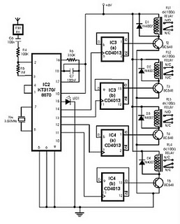
The FM transmitter circuit modulates the DTMF signals onto a carrier frequency, allowing the signals to be transmitted wirelessly. The receiver unit is equipped with a demodulator that captures the transmitted frequencies and converts them back into DTMF signals. These signals are then processed by the DTMF-to-BCD converter, which translates the tones into binary-coded decimal outputs. Each output corresponds to a specific appliance, enabling the user to control multiple devices from a distance.
The use of a 3.58 MHz quartz crystal provides the necessary timing accuracy for the DTMF generator, ensuring that the tones produced are within the required frequency specifications. The design is modular, allowing for easy adjustments and scalability, making it suitable for various applications in remote control systems. Proper layout and component selection are essential to minimize noise and interference, ensuring reliable operation in practical scenarios.Here we make use of DTMF (dual-tone multi frequency) signals (used in telephones to dial the digits) as the control codes. The DTMF tones are used for frequency modulation of the carrier. At the receiver unit, these frequency modulated signals are intercepted to obtain DTMF tones at the speaker terminals.
This DTMF signal is connected to a DTMF-to -BCD converter whose BCD output is used to switch-on and switch-off various electrical appliances (4 in this case) The remote control transmitter consists of DTMF generator and an FM transmitter circuit. For generating the DTMF frequencies, a dedicated IC UM91214B (which is used as a dialer IC in telephone instruments) is used here.
This IC requires 3 volts for its operation. This is provided by a simple zener diode voltage regulator which converts 9 volts into 3 volts for use by this IC. For its time base, it requires a quartz crystal of 3. 58 MHz which is easily available from electronic component shops. Pins 1 and 2 are used as chip select and DTMF mode select pins respectively. When the row and column pins (12 and 15) are shorted to each other, DTMF tones corresponding to digit 1 are output from its pin 7.
Similarly, pins 13, 16 and 17 are additionally required to dial digits 2, 4 and 8. Rest of the pins of this IC may be left as they are. . 🔗 External reference
Related Circuits
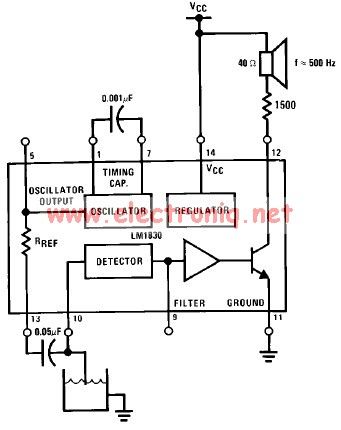
The LM1830 low-level detector can utilize an audio indication (speaker) or a visual indicator (LED - light-emitting diode) that activates when the level is too low. This low-level detector circuit generates a 500 Hz audio signal when the level...
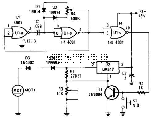
Connected in this manner, an LM317 1-A adjustable-voltage regulator can be utilized to control the speed of a miniature DC motor or to adjust the brightness of a small lamp. The circuit achieves this by modulating the pulse width,...
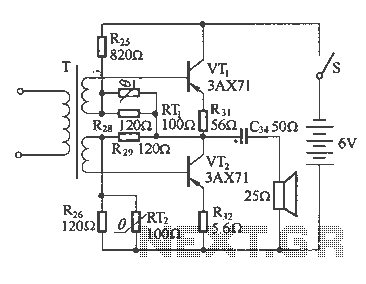
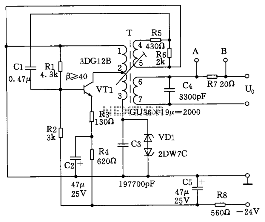
The following diagram illustrates a common output transformerless (OTL) amplifier circuit that delivers an output power of 100 mW. The circuit includes an output transformer and a capacitor, which work in conjunction with speaker units. The frequency characteristics of...
Field strength meters are essential tools for individuals working with radio transmitter electronics. The following is an example of a circuit that serves this purpose. A field strength meter circuit typically consists of several key components, including an antenna, a RF...
The circuit depicted in the figure allows for the selection of optimal operating conditions and a suitable allocation of the temperature coefficient for the resonant circuit components. The resonance occurs at both ends of the circuit. Additionally, the exchange...
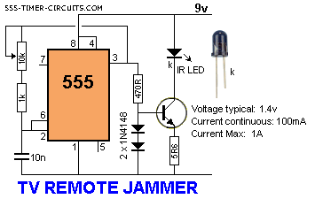
This circuit disrupts the infrared receiver in a television by generating a continuous signal that interferes with the signals from a remote control, thereby preventing the television from detecting channel changes or other commands. This allows for uninterrupted viewing...
Warning: include(partials/cookie-banner.php): Failed to open stream: Permission denied in /var/www/html/nextgr/view-circuit.php on line 713
Warning: include(): Failed opening 'partials/cookie-banner.php' for inclusion (include_path='.:/usr/share/php') in /var/www/html/nextgr/view-circuit.php on line 713