
IR remote control computer interfacing

The circuit design for interfacing an IR remote controller with a computer involves several key components and configurations. The main elements include an IR receiver module, a 7555 timer IC, and a power transistor for driving IR LEDs. The IR receiver module, typically tuned to a frequency of 40 kHz, captures the modulated signals from the remote control. This module is essential for filtering out noise and providing a clean digital signal for further processing.
In the proposed configuration, the output from the IR receiver module is connected to the input of the 7555 timer IC. The modification involves disconnecting the wire from pin 4 of the 7555 IC, allowing it to interface with the computer's TTL-level output. This setup enables the computer to send control signals back to the IR transmitter section, effectively allowing two-way communication.
The 7555 timer can be configured in astable mode to generate a square wave signal that drives a power transistor, which in turn controls one or more IR LEDs. The choice of a power transistor, such as a MOSFET, is crucial for efficiently driving the LEDs while ensuring sufficient current flow. The frequency of the timer can be adjusted, with suggestions of operating at 40 kHz or even 80 kHz, where the latter may provide better performance due to a more favorable duty cycle for the modulated signal.
For experimental setups, connecting the circuit to a PC's parallel port provides a straightforward method for data transfer. The parallel port can handle multiple data lines, making it suitable for sending commands to the circuit. Additionally, using a joystick port for the receiving section simplifies the design, as it provides both input lines and power to the circuit.
In summary, the described circuit allows for versatile control of various devices using IR remote signals. With proper configuration and programming, it enables users to create a functional interface between a computer and IR remote controls, facilitating a wide range of applications in home automation and remote device management.This article tries to get you some idea how to interface IR remote controllers to computer. Possible applications could be controlling your computer your TV`s remote control or controlling your VCR using computer. This circuit was posted to sci. electronics newsgroup long ago. This circuit has been very useful to me because I based my first IR remo te control experiments on this circuit. With some little modification the transmitter part of this circuit can be used with computer. The idea is to cut the wire going to 7555 IC pin 4. Connect the wire end coming form receiver to computer input and the end going to 7555 chip pin 4 to one computer output (computer inputs and outputs should be TTL level signals). This circuit is a good example how to do the computer to IR remote interfacing in both ways. All you need is a simple program for sampling the data coming form receiver (few kHz sample rate is enough).
When you want to control something, then just send the sampled data to the transmitter part of this circuit. The circuit can be easily connected to PC parallel port for your experiments. If you are experimenting only with reception, then one good idea might be to connect the receiving part of the circuit to joystick port, because there are easy to use input lines and also poer for the whole circuit.
Newsgroups: sci. electronics From: dplatt@ntg. com (Dave Platt) Subject: Re: Infra Red Retransmitters - For Remote Controllers. Organization: New Technologies Group, Inc. Palo Alto CA Date: Mon, 28 Feb 1994 04:00:25 GMT >1)Several receptors in parallel (arranged in order to have at least >270 degree range) You can probably use the little receiver modules made by Sharp, and marketed by Radio Shack (among other places), in a sort of wired-OR arrangment. Sony TV sets do this internally. the IR receiver is in a wired-OR arrangement with the chip which decodes the front-panel pushbuttons, and the "guts" of the TV simply listen to this signalling bus for their commands.
On my KV-20XBR, at least, the control board of the TV literally cannot tell whether a button-press was on the front panel or on the IR remote. it`s all bits on a Control-S/SIRCS bus by then! [1] Use one of the IR receiver/demodulator modules (or several, in parallel) to receive and clean up the signal, and use this signal to switch a 40 kHz oscillator on and off.
Do _not_ try to receive, amplify, and retransmit the modulated carrier directly. you will probably find that you circuit is extremely noise-sensitive and difficult to "trim". The receiver modules have a tuned 40 kHz amplifier circuit built in, which eliminates _lots_ of noise. [2] You`ll probably want to use a tunable oscillator (such as a CMOS 555 or something like that), and use the oscillator`s output to drive a power transistor (a MOSFET works well), and have the power transistor drive one or more IR-LEDs in parallel.
[3] You can probably get decent retransmission using a 555 tunes to 40 kHz. However, you may get somewhat better retransmission if you run the oscillator at 80 kHz and divide down by two before driving your IR-LED - this will give you a 50% duty cycle rather than the 33%/66% duty cycle of a typical 555 circuit. The closer you get to 50%, the more easily your retransmitted carrier will get through the tuned filter in the receiver.
🔗 External reference
Related Circuits

The system consists of an LK16-5/31 type master controller and a PQY1 Series magnetic control panel, which includes a control circuit. The motor is controlled by limit switches SQ1 and SQ2, which manage the reverse operation. The master controller...
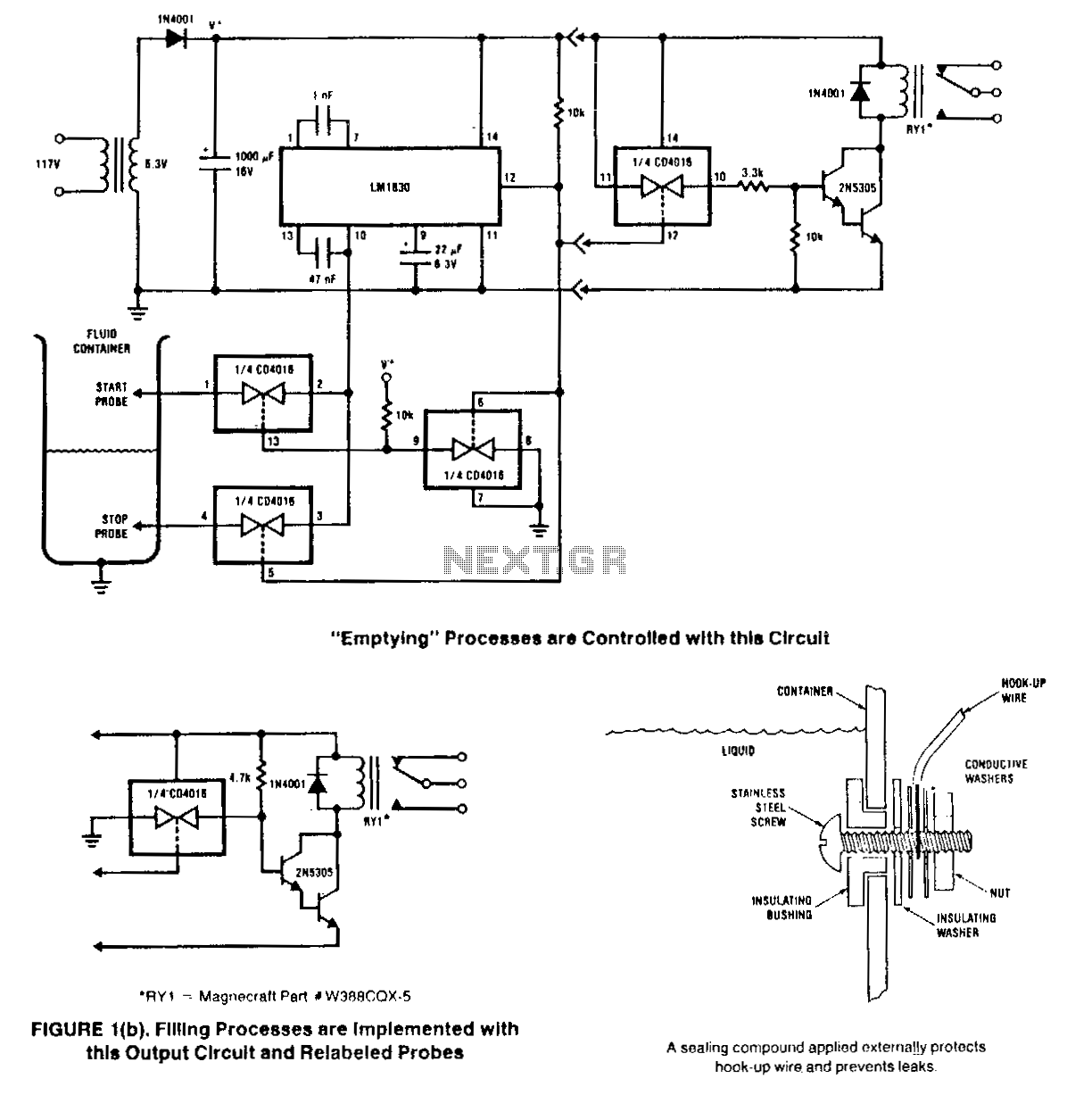
This circuit is designed to detect the presence or absence of aqueous fluids. An AC signal generated on-chip is passed through two probes within the fluid. A detector determines the presence of the fluid by using the probes in...
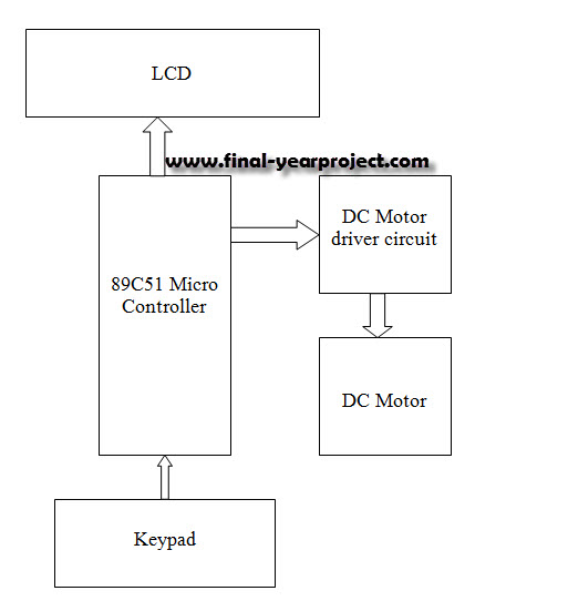
This report details an electronic project focused on the speed control of a DC motor using a microcontroller and PWM (Pulse Width Modulation). The system integrates a microcontroller with an LCD, keypad, and a DC motor driver. The microcontroller...
This circuit enables the switching on and off of appliances through telephone lines. It allows for the control of appliances from any distance, overcoming the limitations of infrared and radio remote controls. The circuit can manage up to nine...
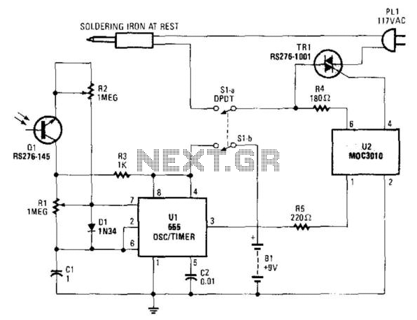
An infrared-sensitive phototransistor is employed to detect the temperature of a soldering iron. The phototransistor must be positioned to view the tip through an opaque tube to prevent interference from stray light, and it is advisable to equip the...
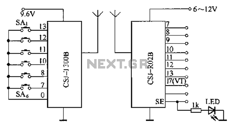
The CSJ-T300B/CSJ-R02B is an enhanced digital encoding and decoding circuit developed based on the CSJ-T300A/CSJ-R02A. It forms a remote control circuit that includes the CSJ-T300B and CSJ-R02B components, as illustrated below. The CSJ-T300B/CSJ-R02B circuit architecture is designed to facilitate improved...