
infrared toggle switch for home

When a key on the remote is pressed, the output of the IR receiver module transitions to low, causing the BC557 to turn on and off rapidly. When activated, the capacitor charges through the collector current of the BC557, and when deactivated, it discharges through the 100K resistor. However, due to the rapid pulse rate (38,000 pulses per second), the capacitor does not fully discharge. Consequently, each key press from the IR remote generates a positive clock pulse at the collector of the BC557 transistor.
Next, the CD4017 decade counter counts the low-to-high pulses at its CLK pin (14) up to 10 and pulls the corresponding output (Q0-Q9) high. Upon initial activation, Q0 goes high, and when the first low-to-high pulse is received at the CLK input (triggered by a key press on the IR remote), Q0 transitions low while Q1 goes high. The Q1 output is connected to an LED through a current-limiting resistor to indicate the ON/OFF status. Additionally, the Q1 output drives a relay switch through an NPN transistor (BC547). A 5V DC relay requiring approximately 70mA of current from a 5V source is used to turn ON the appliance, with the current supplied by the BC547.
The overall design allows for seamless integration of IR control into existing appliances, enhancing their functionality and user convenience. The circuit is compact, efficient, and capable of operating with a variety of IR remote controls, making it a versatile solution for remote operation of electrical devices.The infra-red (IR) toggle switch project described here is aimed to provide control mechanism for electrical appliances that do not have remote operation features. The goal is to construct a black box where you can plug-in your 120V AC appliance and control ON and OFF operations with any modern IR remote control devices.
Modern IR remote controls generate modulated pulse train of 38KHz frequency when any key on the remote is pressed. With the use of capacitive filtering we will convert the stream of pulses into one pulse regardless of the key entered. This way, we will be able to toggle a relay switch with any key pressed on the remote. This project has been tested with varieties of IR remote control devices like that for TV, DVD, digital camera, etc.
, and it worked well. The TSOP 1738 IR receiver module detects the 38KHz input pulses received from the IR remote control device. Under stand-by condition, the output pin of the IR module is at logic High, and when it detects the train of pulses, they appear at its output.
The output from IR receiver is fed to a PNP transistor (BC557) with a series base resistor of 4. 7K. At the collector of the NPN transistor, the train of pulses will be inverted. There is a 10uF capacitor and 100K resistor connected from the collector to ground. The function of capacitor is to convert the train of pulses into a single pulse, and the resistor is to provide the discharge path for the capacitor. So lets see what happens when a key on the remote is pressed. During standby, the output of IR receiver module is High, so BC557 is cut off. The capacitor is fully discharged, and the collector of BC557 is at ground. When a key is pressed on the remote, the train of pulses arrived at the base of BC557 turns it ON and OFF very fast.
When it is ON, the capacitor gets charged through the collector current of BC557, and when it is OFF, the capacitor starts to discharge through 100K resistor. But the train of pulses is so fast (38000 pulses per second) that the capacitor doesn`t get chance to discharge.
So, the bottom line is, every time a key is pressed from the IR remote, a positive going clock pulse is generated at the collector of BC557 transistor. Next comes CD4017, a decade counter. It counts low-to-high going pulses up to 10 that are arrived at its CLK pin (14) and pulls the corresponding output (Q0-Q9) High.
When it is just turned on, Q0 goes High, and when it gets a first low-to-high pulse (when a key is pressed from the IR remote) at CLK i/p, Q0 goes Low and Q1 goes High. Q1 output is connected to a LED through a current limiting resistor to indicate the ON/OFF status. The Q1 output is also used to drive a relay switch through a NPN transistor (BC547). I used 5V DC relay that requires about 70mA current from 5V source to turn ON. This current is provided by BC547. 🔗 External reference
Related Circuits
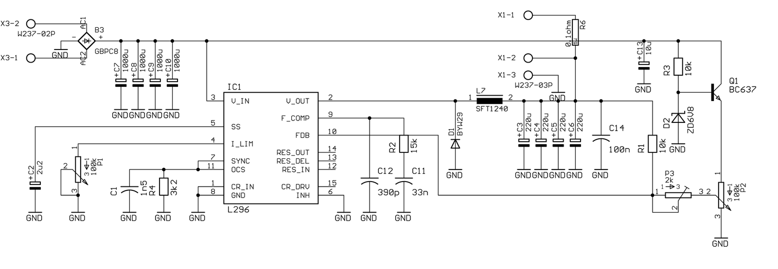
Specifically for the chip used in this circuit, the data is as follows: The oscillator operates at a frequency of 200 kHz, with output noise below 1% (worst case). The maximum current is 4 A at 20 V. The...
The AD8205 can be utilized to create a high-side current sensing circuit with a low-side switch. In this configuration, an inductive load (such as a solenoid) and a resistive shunt are incorporated. The resistive shunt is positioned on the...
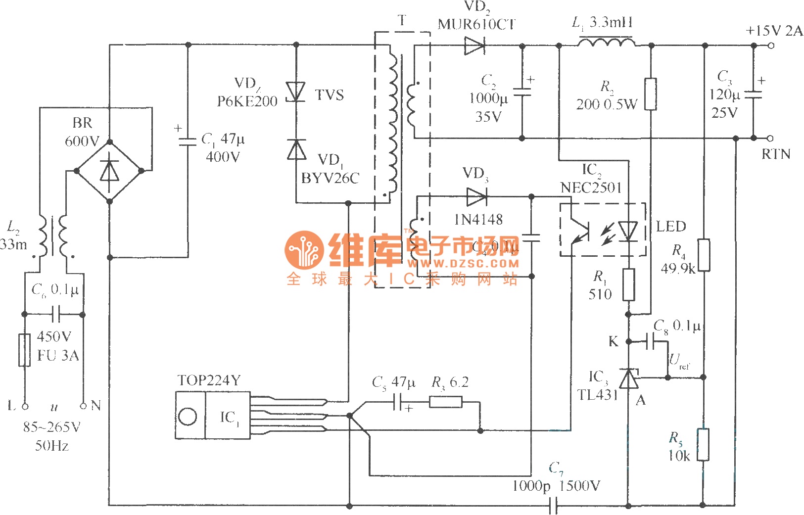
This document presents a 30W micro switch regulated power supply utilizing the TOP224Y integrated circuit. The circuit diagram illustrates its design. A notable feature of this power supply is the use of the TL431 component to replace the regulation...
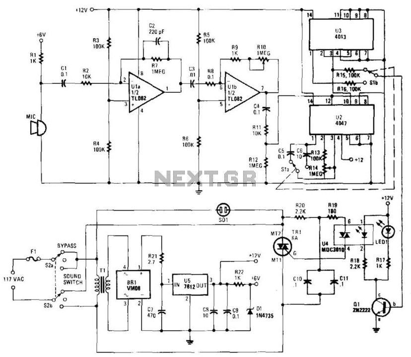
This circuit provides either latched switching or timed switching. U1A and U1B provide audio amplification from the microphone. U2 is a retriggerable monostable multivibrator. S1A and S1B select either U3, a flip-flop, or U2. R13 and R14 allow a...
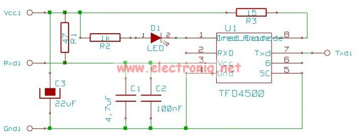
This electronic infrared adapter serial transceiver circuit is based on a TFDS4500 IC and can be used to transmit data from portable devices to a PC using infrared (IR) and a serial port. The TFDS4500 infrared adapter is a...

This circuit is a simple remote-controlled relay capable of switching lamps or other devices. D1 can be a phototransistor, LDR, or an infrared transistor. The circuit is controlled using an IR remote, similar to a TV remote control, when...