
Switching power supply Regulator 0-40V 4A by L296
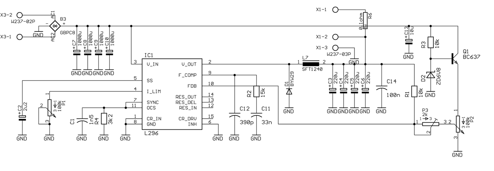
The described circuit utilizes a specialized chip that features an oscillator operating at a frequency of 200 kHz. This frequency is critical for ensuring the stability and performance of the circuit. The output noise level is maintained below 1%, even under worst-case conditions, which indicates a high-quality signal output that minimizes interference and distortion.
The circuit is capable of delivering a maximum current of 4 A at an operating voltage of 20 V. This allows for a robust performance suitable for various applications requiring significant power. The voltage regulation capability extends from 0 V (true zero) to 40 V, enabling flexibility in output voltage settings, which can be crucial for applications that necessitate precise voltage levels.
Both the voltage and current limits are adjustable, providing the user with the ability to tailor the circuit's performance to meet specific requirements. This feature is particularly beneficial in applications where load conditions may vary or where specific operational parameters must be adhered to.
Attention must be given to the selection of the choke within the circuit. The ferrite material used in the choke should be rated for frequencies up to 300 kHz to ensure optimal performance and efficiency. This consideration is vital to prevent losses and maintain the integrity of the circuit's operation.
The input to the regulator is versatile, accommodating both DC and AC voltage sources, thanks to the integration of a rectifier bridge. This design choice enhances the circuit's adaptability, allowing it to function effectively in various power supply scenarios.
Overall, the circuit design emphasizes stability, performance, and flexibility, making it suitable for a wide range of electronic applications.Specificaly for the chip that is used in this circuit data are like this: Oscilator runs at freq 200kHz, output noise is below 1% (worst case), max current is 4A at 20V. Voltage can be regulated from 0, 0 V (true zero), to 40 V. Voltage and current limit, can be adjusted. You should take special care when purchasing choke. Its ferrite material shou ld be build for frequencies up to 300kHz. Input to the regulator can be DC or AC voltage becouse the input is rectifier bridge. Disclaimer All files are found using legitimate search engine techniques. This site does not and will not condone hacking into sites to create the links it list. We will and do assume that all links found on the search engines we use are obtained in a legal manner and the webmasters are aware of the links listed on the search engines. If you find a URL that belongs to you, and you did not realize that it was "open to the public", please use the report button to notify the blogmaster of your request to remove it or it will remove within 24 hours.
This is not an invitation for webblog haters to spam with requests to remove content they feel that is objectionable and or unacceptable. Proof of URL ownership is required. NOTICE: This Blog Has Already Been Reviewed And Accepted By Blogger. com 🔗 External reference
Related Circuits
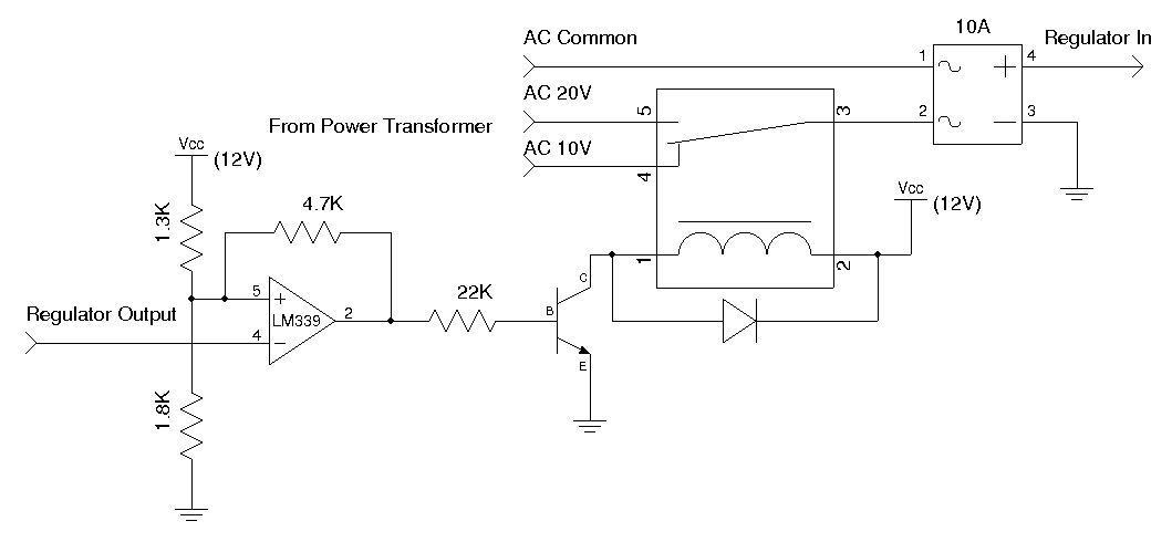
A used 250VA power transformer has been removed from equipment recently. The transformer features a dual 10V AC output along with several auxiliary voltage outputs. The 10V winding is rated for 10A, making it suitable for a high current...
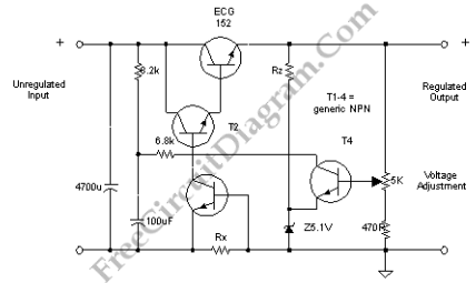
This discrete voltage regulator features capabilities equivalent to modern voltage regulator integrated circuits (ICs). While constructing a discrete version may not be cost-effective, studying the schematic diagram provides valuable insights into its operation. The circuit includes a resistor of...
Buffering for the zener diode is achieved through the impedance matching and current amplifying features of the emitter follower, which draws less current from the zener. Buffering in electronic circuits is essential for ensuring that the performance of one component...

This circuit performs a rapid battery test without requiring a power supply or costly moving-coil voltmeters. It features two ranges: when SW1 is configured as depicted in the circuit diagram, the device can test batteries ranging from 3V to...
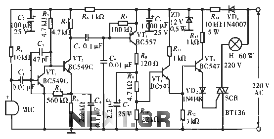
The circuit utilizes condenser microphones to detect sound and convert it into signal variations. This signal is then processed through directly coupled transistors VT1 and VT2, which form an amplification stage before being fed into a switching circuit. The...
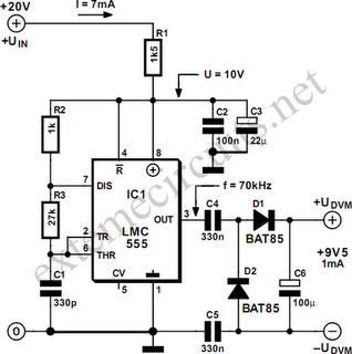
This circuit is constructed using the widely recognized LMC555 timer integrated circuit (IC). It is commonly employed in laboratory power supplies and various test and measurement equipment. The LMC555 timer IC is a versatile component that can be configured in...