
Infrared Wireless Headphones circuit
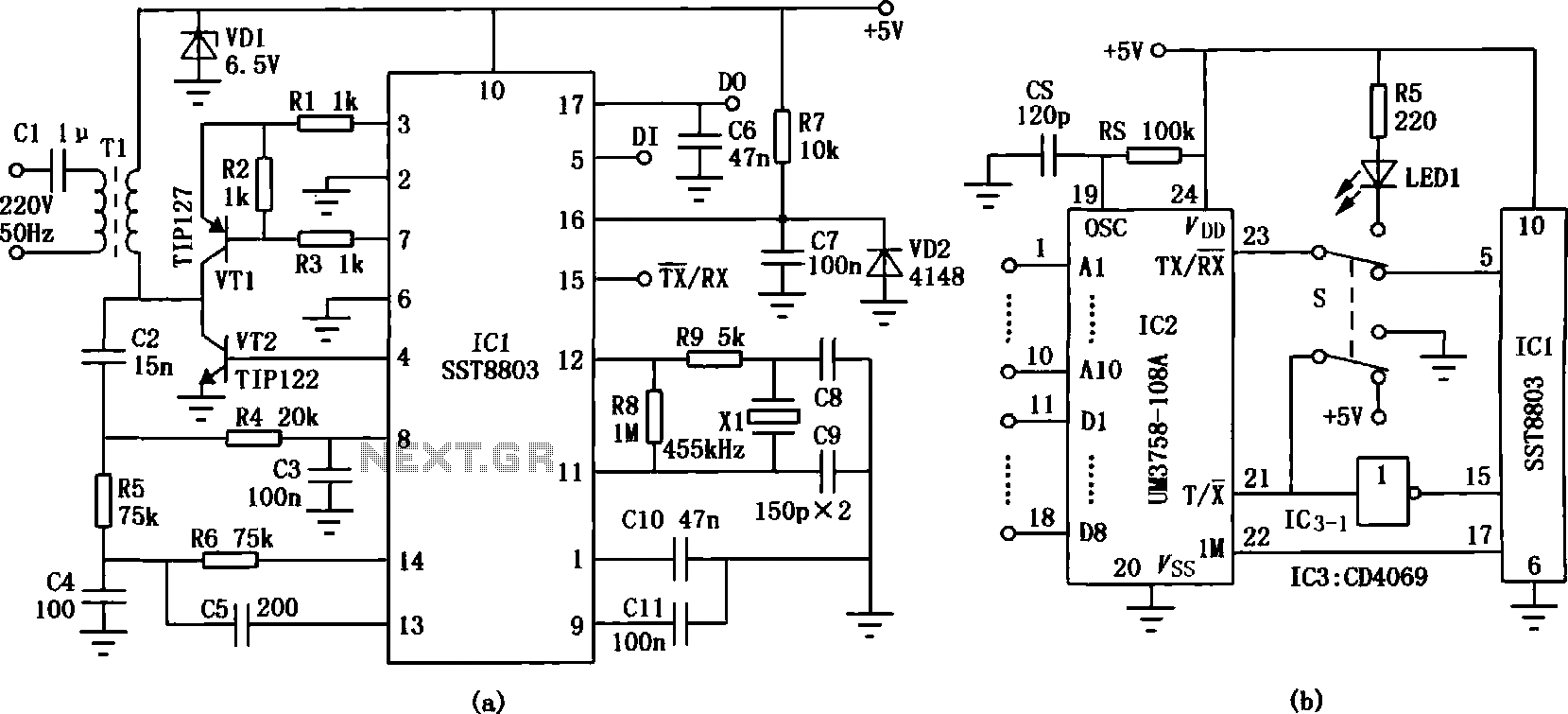
The infrared wireless transmission circuit consists of two main components: the transmitter and the receiver. In the transmitter circuit (Figure (a)), the headset plugs into the audio jack of a TV or tape recorder. The audio signal is passed through a capacitive coupling (C1) and amplified by transistors (VT1), which then drives the infrared emitting diodes (VD1 and VD2) to emit audio waves in the infrared spectrum. The bias resistor (R2) is adjusted to ensure a quiescent current of 10 mA flows through the diodes.
The receiver circuit for the infrared wireless headphones is illustrated in Figure (b). Here, the infrared receivers (VD3 to VD5) capture the infrared signals emitted from the transmitter and convert them back into audio signals. These signals are then amplified by transistor (VT2) and further processed by an integrated operational amplifier (IC1) for power amplification, ultimately delivering the audio output to the headphones. The design employs three infrared receivers to ensure a full range of signal reception. During the debugging process, the positive terminal of the infrared receiver tube is touched to adjust resistances (R4 and R5) for optimal output, minimizing hum in the headphones. Subsequently, the transmitting circuit is activated, and the volume of the TV or tape recorder is adjusted to achieve clear sound in the earpiece.
This schematic showcases the advantages of infrared technology in wireless audio transmission, highlighting its versatility for various applications both indoors and outdoors. The design emphasizes ease of use and flexibility, making it an effective solution for wireless audio needs.Since the transmission circuit inductive wireless headset must be fixedly mounted on a wall or ceiling of a room, it can not be used outdoors, which is a major drawback inductive wireless headphones. The infrared wireless headset is not, due to its signal transmission uses a compact infrared transmitter circuit, both indoors and audio signals for radio reception electronic teaching, home television and audio equipment, but also the use of portable tape recorders, CD, VCD outdoors and MP3, the easily remove headset line, and truly wireless "Walkman."Infrared wireless transmission circuit of FIG earphone (a) in Fig. XP will plug into the TV when using tape recorders inside the headphone jack, the audio signal through XP via capacitive coupling Cl, transistors VTl amplification, and then launching a audio wave infrared VDl outward from the infrared emitting diode and VD2.
After properly adjusting the bias resistor circuit pretend R2, flowing through VDl and VD2 quiescent current l0mA can.Figure (b) for the receiver circuit infrared wireless headphones. After the infrared receiver VD3 ~ VD5 receives infrared signals emitted from the transmitting circuit to convert it into an audio signal, and then by the transistor VT2 amplified into integrated operational amplifier ICl for power amplification, and finally by BE headphone output.
Circuit using three infrared receiver is to be able to receive the full range signal. When debugging, the positive first hand touch infrared receiver tube, adjust the resistance R4, R5 output of the headset BE hum loudest, and then turned on the transmitting circuit, appropriately adjusting the volume of the TV or tape recorders size until the earpiece loud and clear so far.
Related Circuits
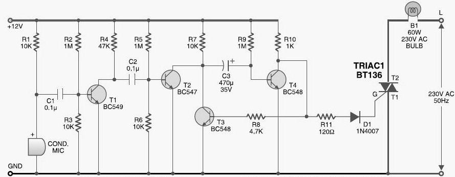
This DIY sound-activated lights circuit turns a lamp on for a brief duration when a dog barks or when a relatively loud sound is detected, creating the impression that the occupants are alerted. The condenser microphone is positioned to...

An A/D converter by National Semiconductor (ADC0838) converts 0 to 5 V analog inputs into a digital data format. A 9 V battery is utilized. The converter connects to the pointer port connector through a 25-pin connector. The ADC0838 is...
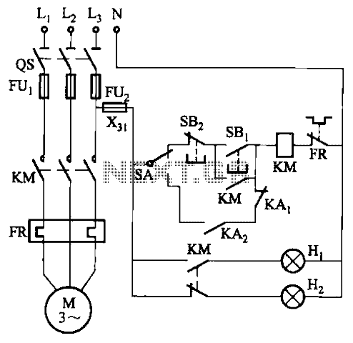
In certain locations near the reservoir or well, when the water level is constrained by the water towers, there is a need for simultaneous monitoring of the water towers and reservoirs as part of an automatic water control system....

The TDA7000 features a Frequency-Locked-Loop (FLL) system with an intermediate frequency of 70 kHz, and selectivity is achieved through active RC filters. The only calibration required is for the resonant circuit associated with the oscillator, which is necessary for...
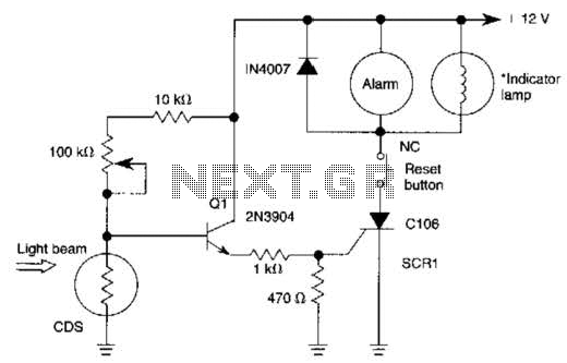
When the light beam that falls on the CDS photocell is interrupted, the transistor (EN3904) conducts, triggering SCR1 (CI06) and activating the alarm bell. SI resets the SCR. The alarm bell should be a self-interrupting electromechanical type. The lamp...

SI and S2 must be pressed within 200 ms of each other to activate K1. The hold time is adjustable via K7. Additionally, the overlap time of SI and S2 can be modified by changing C1 and C2 or...