
Light-Beam Alarm For Intrusion Detection Circuit

The circuit operates as a light interruption alarm system utilizing a CDS (Cadmium Sulfide) photocell to detect changes in ambient light conditions. When an object interrupts the light beam directed at the CDS photocell, the resistance of the photocell decreases, leading to an increase in the voltage across it. This change in voltage is sufficient to turn on the EN3904 transistor, which serves as a switch in this configuration.
Once the EN3904 transistor is activated, it allows current to flow to the gate of the SCR1 (CI06), turning it on. The SCR is a semiconductor device that can latch on, meaning that once it is triggered by the EN3904, it will continue to conduct even after the triggering voltage is removed, as long as the current through it remains above a certain threshold. This characteristic is crucial for maintaining the alarm state.
The alarm bell, which is of the self-interrupting electromechanical type, is connected in such a way that it will sound when SCR1 is conducting. The design specifies that the lamp associated with the alarm should draw a minimum of 100 mA. This ensures that the current flowing through SCR1 remains above the holding current required to keep it in the on state during the alarm cycle.
To reset the SCR and silence the alarm, a switch (SI) is incorporated into the circuit. When SI is activated, it interrupts the current flowing through the SCR, allowing it to turn off and thereby resetting the system. The overall design emphasizes reliability and responsiveness to light interruptions, making it suitable for applications such as security systems or automated alerts. When the light beam that falls in the CDS photocell is interrupted, transistor (EN3904) conducts thereby triggering SCR1 (CI06) and activating alarm bell. SI resets the SCR. The alarm bell should be a self-interrupting electromechanical type. Lamp should draw at least 100 mA to sensure SCR1 remaining on during alarm cycle 🔗 External reference
Related Circuits

Low-frequency signals produced by transducers, measurement equipment, or data loggers often resemble the first waveform in the figure. The circuit operates as a tracking sample-and-hold, where transients are replaced in the output by the stored value of the current...
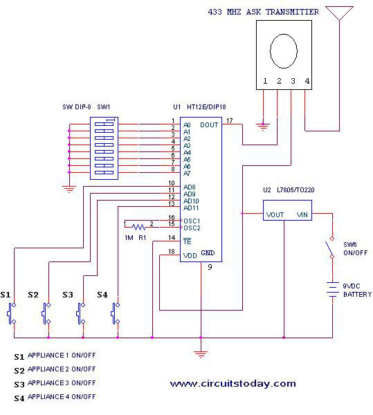
This project outlines a simple remote control system utilizing RF communication without the use of a microcontroller. The remote is designed for various home appliances such as televisions, fans, and lights, providing significant convenience by allowing operation from a...
Figure 1-89 illustrates a loudness control circuit. A potentiometer is connected to ground, with 30% of the total resistance at the tap. When the slider arm is adjusted to the tap position, a midrange attenuation of 30 dB is...
This document provides an overview of a simple circuit diagram for frequency (F and V) voltage conversion. It describes a digital frequency meter circuit primarily based on the LM555 timer IC, which is commonly used in various applications, including...

Although labelled as distortion, this is a soft clipping device, using germanium diodes. It's a good example of how little you need for a good basic sound. You could easily swap (or switch) these diodes to silicon types for...

The circuit consists of two balanced components forming a simple Beat Frequency Oscillator (BFO) metal detector. The BFO utilizes a ready-assembled and tested circuit board with a PIC 12F675 chip at its center. This passive detector employs a detector...