
Solid-State Tesla Coil
The Solid State Tesla Coil represents a significant advancement in Tesla coil design, prioritizing operator safety while maintaining the functionality required for educational demonstrations and experiments. The elimination of high-voltage transformers reduces the risk of electrical shock, making this design more accessible to hobbyists and educators. The use of a 555 timer as a pulse generator offers precise control over the operation of the coil, allowing for adjustable frequency and duty cycle. The bridge rectifier and filter capacitors ensure that the power supply delivers a stable DC voltage, which is critical for reliable operation.
The circuit's design emphasizes a modular approach, allowing for easy assembly and troubleshooting. The choice of components, including the use of an automobile ignition coil, is both practical and cost-effective, making it feasible for individuals to replicate the design. The tuning method employed for the primary coil enhances the coil's performance, enabling operators to optimize the output voltage.
Overall, the Solid State Tesla Coil schematic provides a comprehensive framework for constructing a high-voltage coil that is both effective and safer than traditional designs. The detailed components list and schematic diagram serve as essential references for builders, ensuring that each element is correctly implemented for optimal performance.Most Tesla coils designed for educational and experimental purposes use line-operated, step-up transformer-in setups like that shown in Fig. 1 -to generate the high voltage needed for the coil`s primary circuit. While there`s nothing technically wrong with that approach, it can place the operator in harm`s way if the coil`s primary circuit is accidentally touched.
CAREFUL! A shock from the high-voltage winding could prove extremely dangerous and may be fatal! Our version, the "Solid State Tesla Coil" (see photos), eliminates the line-operated, high-voltage transformer, making it a safer project to build and to experiment with. Even so, wise operators will keep their digits out of the wiring while the coil is under power. The schematic diagram for the Solid-State Tesla Coil is shown in Fig. 2. In that updated version of the Tesla experiment, an 18-volt, 2-ampere transformer (T1), a bridge rectifier circuit (consisting of D1-D4), and filter capacitors (C1and C3) supply operating power for the coil circuitry.
A 555 timer/oscillator (U1) is configure as a self-oscillating pulse-generator circuit. Resistors R1 and R2 make up a voltage-divider network, which is used to lower the 24-volt DC output of the power supply to a safe operating level for U1. The 555`s narrow output pulse at pin 3 supplies drive current to the base of Q1. Transistor Q2 supplies sufficient current to transistors Q3 and Q4 to drive those components into full saturation.
The primary winding of T2 (an automobile ignition coil) is connected in series with Q3 and Q4, and across the power supply. Transistors Q3 and Q4 operate like a toggle switch, connecting the coil across the power source at the rate and on-time set by U1.
That high-current pulse generates a rising and collapsing field across the primary winding of T2. The filed causes a current to be induced in the secondary winding of T2. The secondary output of T2 is fed across three 500pF, 10 kilovolt doorknob capacitors (collectively designated C5) that are parallel connected and tied across the high-voltage output of T2 as an energy-storage device. Those capacitors charge up to T1`s secondary voltage and are then discharged through the spark gap and the primary (L1) of the Tesla coil, producing higher voltage in the secondary of the coil (L2).
of the secondary coil. Because variable 10-kilovolt capacitors are about as common a Condor eggs, some other means must be used to tune L1. The simplest method is to tap the primary coil on every turn and select the tap that produces the greatest voltage at the hot end of L2.
The author`s prototype was built breadboard style on an 11x11x1-inch wooden cutting board (see photos), but any similar non-conducting material (perhaps plastic) will do. The majority of the small components, as shown in the photos, were mounted on a 3x5-inch section of perfboard, and point-to-point wiring techniques were used to complete the connections.
Refer to the schematic diagram (in Fig. 2) and the photos for wiring and general parts-layout details. Note: Components T1 and T2, C5, Q3 and Q4, F1, and S1 are not mounted to the perfboard (see photos). Figure 3 shows the positioning of the perfboard and off-board components on the baseboard. Mount the fully-populated perfboard assembly to the b 🔗 External reference
Related Circuits
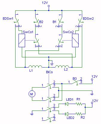
This is a fun and non-dangerous project for those people who like to throw projectiles magnetically. It simply works by placing a ferromagnetic projectile at one end of a coil and pulsing some power in it. The trick is...
Tuning a system is typically a challenging task. The user must power the system, observe the spark length, shut it down, adjust the primary tap, restart, and repeat this process until the spark length is optimized. However, using a...
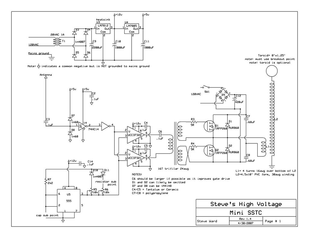
This instructable provides detailed instructions for constructing a solid-state Tesla coil based on Steve Ward's mini SSTC schematic. The solid-state Tesla coil (SSTC) is an advanced high-frequency resonant transformer that operates without the need for mechanical components such as spark...
A coil is wound around a non-conductive tube, which serves as the barrel of the coilgun. The tube must be made from a non-conductive material, such as plastic, to prevent the coil's magnetic field from canceling itself out within...
Latching is achieved by storing the gate trigger energy from the preceding half-cycle in capacitors. Power must be interrupted for more than one full cycle of the line to ensure turn-off. Resistor R and capacitor C are selected to...

The disk magnets are attracted to each end of the power coil. The coil is pulse charged, causing the permanent magnetic field to push away from the center of the coil. When the electromagnetic field collapses in the coil,...