
Lighting auto controller
The last feature is particularly useful for providing a delay after the switch is activated. Once switch S1 is turned ON, capacitor C2 starts charging through resistors R1 and C1, as well as bridge rectifier D1-D4. Zener diode D5 limits the voltage across capacitor C2 to approximately 15 V. After a short duration, LED D6 lights up, which causes a significant drop in voltage across resistor R3. This change in voltage triggers Triac TR1, which subsequently powers the lamp connected to terminal K2. It is important to note that resistor R3 functions as a light-dependent resistor (LDR), with resistance varying based on the intensity of light incident on it. When the switch is turned OFF, capacitor C2 discharges through resistors R1, R2, and LED D6. During the discharge phase, LED D6 dims gradually, leading to a continuous reduction in voltage across R3. The increasing resistance of R3 alters the firing angle of the Triac, resulting in a smooth decrease in the lamp's brightness. The time required for the lamp to turn off completely is determined by the adjustable potentiometer P1 and is directly related to the time constant defined by resistors R2 and capacitor C2. The circuit functions correctly only when the light incident on R3 is primarily from LED D6 rather than ambient room light. The specific type of LDR is not critical, although a 5mm length is recommended.
The circuit utilizes a simple design that incorporates essential components to control the light intensity of an incandescent lamp effectively. The use of a Triac allows for efficient power control, while the integration of a Zener diode ensures voltage regulation, protecting sensitive components. The gradual dimming effect achieved through the discharge of capacitor C2 enhances user experience by providing a smooth transition in brightness, avoiding abrupt changes that could be visually jarring. Proper placement of the components on the circuit board is crucial to ensure optimal performance and reliability, particularly in terms of heat dissipation and electrical isolation. The choice of an LDR for R3 plays a significant role in the circuit's responsiveness to light conditions, making it adaptable to various lighting environments. Overall, this light intensity governor represents a practical solution for controlling incandescent lighting with a focus on user comfort and circuit efficiency.The governor following is intended to regulate the light intensity incandescent 220 V. The components in a relatively few, which means it can easily be mounted onto a small plate. After the build, we recommend you place it inside the box which is flush mounted switch ON / OFF the lamp. Setting the switch to ON, the lamp will light after about 400 msec, a delay is probably negligible. But when the state enters the ON OFF, then mesolathei a period of 20 sec, the brightness of the lamp remains unchanged to start falling out soon after.
The last feature is particularly useful when we want to have a little time from the moment you 'close' switch. Once the switch S1 set to ON, the capacitor C2 begins to charge through R1, C1 and bridge D1-D4. The Zener diode D5 limits the voltage across the capacitor to about 15 n. After awhile, the diode D6 LED illuminates, causing the appearance of a significant drop in voltage across R3.
The change in voltage results in stimulation of Triac TR1, which in turn lit the lamp is connected to K2. We note that the resistor R3 is a type of LDR, the price that depends on the intensity of light falling on it.
When the switch is moved to OFF, the capacitor C2 will discharge through R 1, R2 and D6. During discharge, the LED D6 reduces the brightness continuously, which causes a gradual decrease in voltage across R3. The increasing resistance of R3 is causing in turn change the firing angle of the Triac, which eventually results in a smooth decrease in brightness of the lamp.
The time required for complete extinction of the lamp is defined by the regulatory P1 and directly dependent on the time constant R2-C2. The circuit works properly only if it falls on the R3 only light diode O6 rather diffuse room light. The type of LDA is not critical. Choose a length with a 5mm. 🔗 External reference
Related Circuits
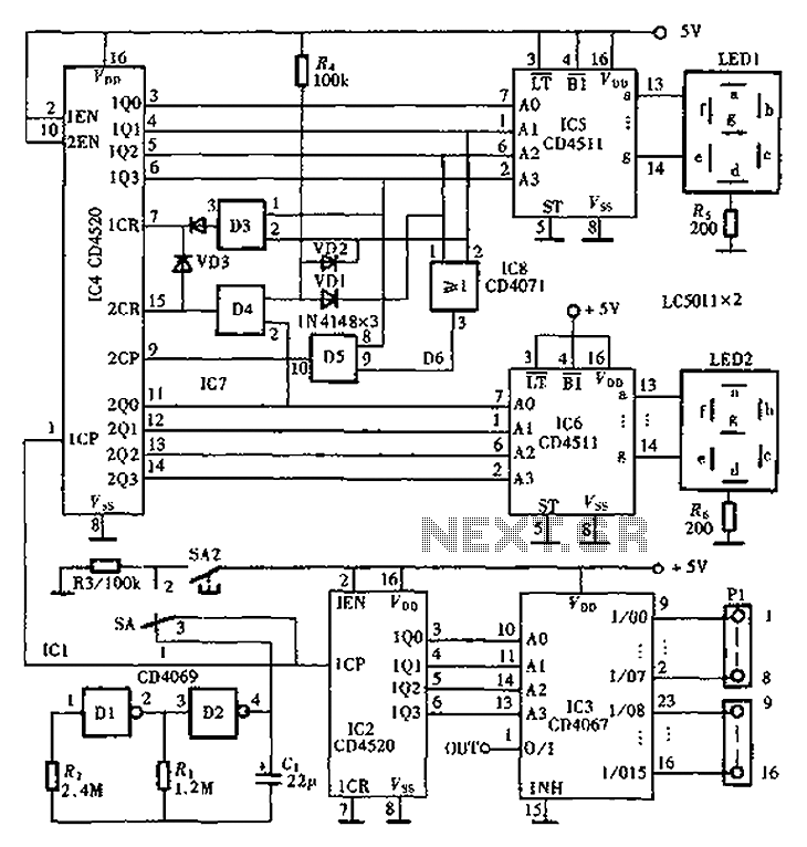
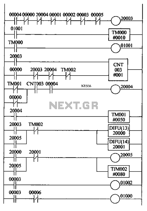
An automatic inspection circuit designed for the simultaneous detection and control of multiple production equipment. This inspection circuit can perform sixteen regular inspections of production equipment. It consists of a pulse generator, multiple inspection circuits, and an automatic inspection...
TL072 is a low-noise JFET input operational amplifier characterized by features such as a common-mode input voltage range, high slew rate, operation without latch-up, compensated internal frequency, high input impedance at the JFET input stage, low noise, low total...
An automatic reclosing PLC control program has been developed based on the specifications for automatic reclosing devices and PLC I/O definitions. The design includes a ladder-shaped diagram with the following features: 1) When the circuit breaker closes, the K4...
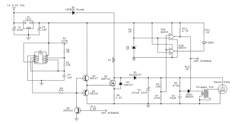
The circuit utilizes an IRF740 MOSFET, which has a maximum drain-source voltage (V_DS) rating of 400V. The avalanche voltage is calculated to be approximately 3520V, indicating that up to about 500V of inductive kickback voltage can develop in the...
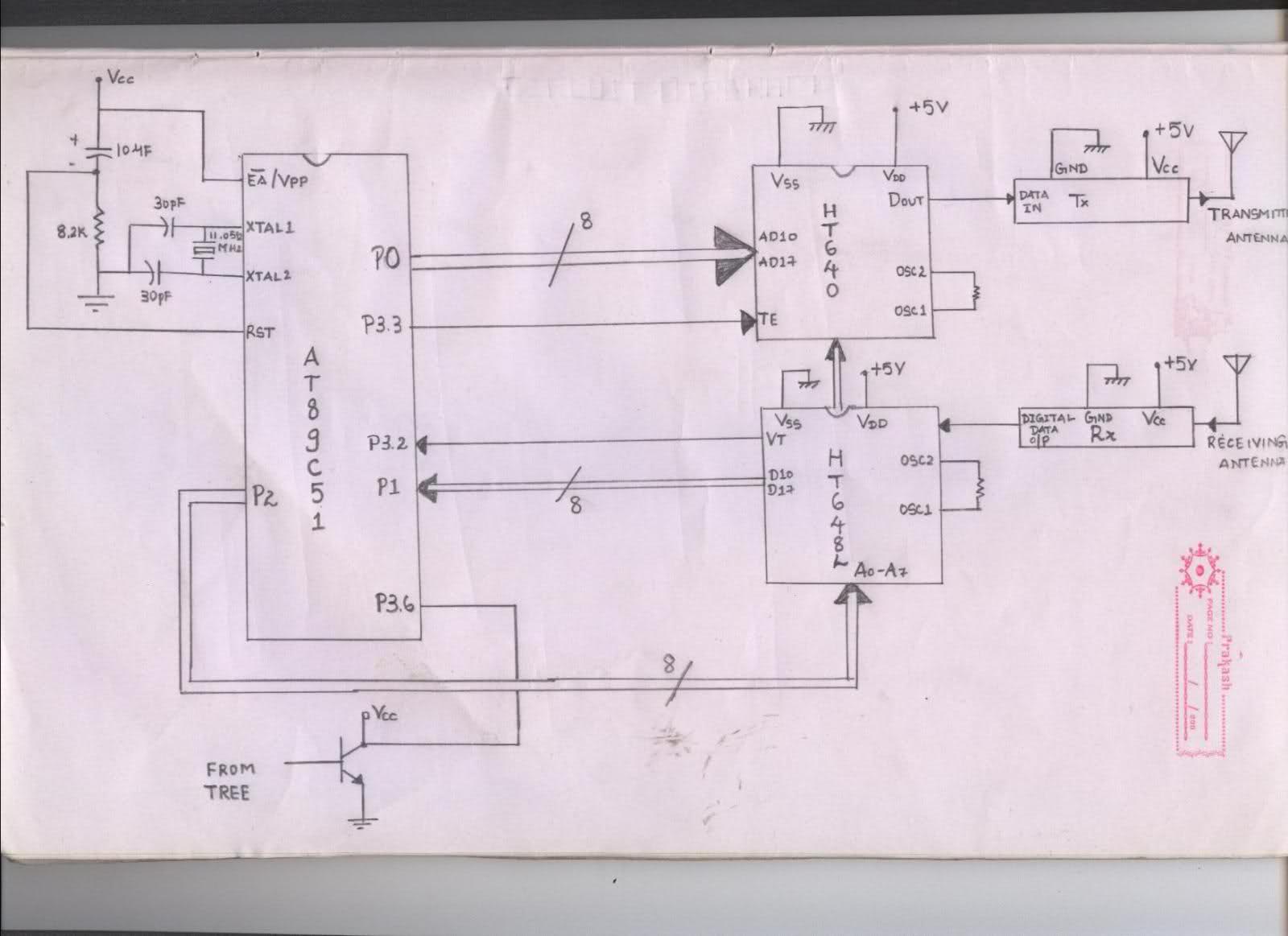
The issue arises when connecting the 8051 microcontroller to the HT640 encoder; the data sent is not received at the receiver. However, when the connections to the 8051 are removed, the transmission functions perfectly. This indicates that manual RF...
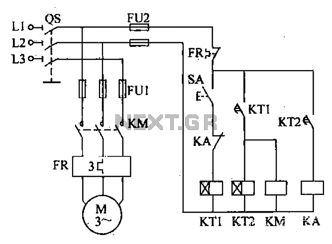
After the power switch is activated, the motor does not start immediately but instead has a specified delay period. This setup allows the machine to perform automatic intermittent lubrication control. The circuit for the motor boot delay and intermittent...