
Isolated send receive ring circuit diagram XTR105 RCV420

The circuit design begins with the RTD (Resistance Temperature Detector) sensor, which operates by varying its resistance in response to temperature changes. The XTR105 is a precision current loop transmitter that converts the resistance change into a proportional voltage signal. This voltage is then converted into a 4 to 20 mA current output, a standard in industrial applications for ensuring reliable signal transmission over long distances.
Twisted pair wiring is utilized for the transmission of the 4 to 20 mA signal to minimize electromagnetic interference, which is critical in environments with high levels of electrical noise. The RCV420 receiver is designed to accurately convert the current signal back into a usable voltage signal. This receiver is particularly effective in maintaining signal integrity over long distances.
The ISO122 isolation amplifier plays a crucial role in protecting the measurement system from ground loops and high common-mode voltages, ensuring that the output voltage remains stable and within the desired range of 0 to 5V. This isolation is vital for maintaining measurement accuracy and system reliability, especially in industrial settings.
Furthermore, the circuit’s design allows for flexibility in RTD connection configurations. The three-wire RTD connection method compensates for lead resistance, enhancing measurement accuracy. However, if a two-wire RTD configuration is preferred, the removal of RLIN2 is necessary to adapt the circuit accordingly. Overall, this circuit design is optimized for robustness, accuracy, and adaptability in various temperature measurement applications. As shown in FIG later, RTD temperature collected in the field, which was converted into a voltage by the XTR105 voltage is converted into 4 ~ 20mA current output, and then the twisted pair transmission, received by RCV420, after isolation amplifier ISO122 isolation amplifier, output 0 ~ 5V voltage. Excellent anti-jamming performance of the circuit can be used for long-distance transmission interference or big occasions.
The figure for the three-wire RTD connection, if used for two-wire RTD connection, remove RLIN2.
Related Circuits
When the infrared receiver tube PH302 receives a signal from the remote control, the CX20106A selected frequency amplifier outputs a low-frequency signal. The low-level signal charges capacitor C through diodes D and R, causing the negative side potential of...
The 3GPPFDD_UE_RX is a test bench designed for testing the user equipment receiver in 3GPP FDD systems. It allows users to connect to an RF circuit device under test (DUT) and evaluate its performance through predefined measurements. This test...
The VU meter operates in conjunction with the integrated amplifier circuit. The audio signal is processed by the audio amplifier circuit, which drives the VU meter to display the audio level. The VU meter circuit is designed to visually represent...
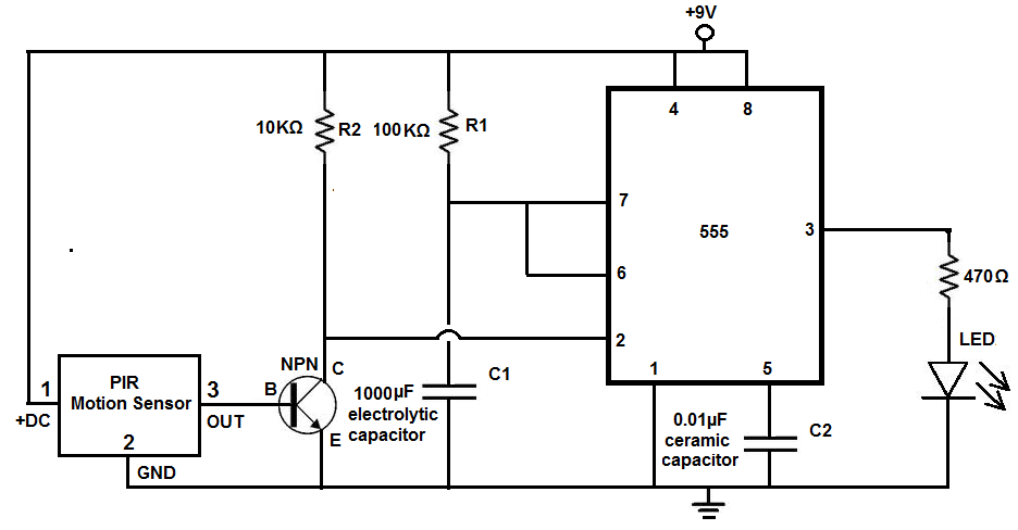
Many individuals install motion detectors in their backyards or homes to automatically turn on lights when movement is detected. Motion sensor lights have gained popularity and are increasingly utilized in various settings. Businesses frequently employ them in bathrooms, where...
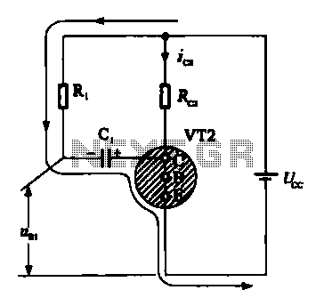
When VRI is off, 0 [2 is activated, allowing current to flow through RJ and Ci. When VT1 conducts, charging of C1 begins, causing it to discharge. This results in an inverting charge on C1, making the voltage positive,...

The sensor must be positioned at an angle of approximately 30 to 45 degrees relative to the ground. This orientation facilitates the drainage of rainwater, preventing accumulation that could trigger the alarm due to water retention on the sensor....