
Intercom
The intercom system is designed for versatility and ease of use, allowing seamless integration of various audio sources. The noise-cancelling microphone and windsock enhance audio clarity, particularly in noisy environments, making it ideal for use in helmets during activities such as motorcycling or cycling. The audio isolation transformer serves a critical role in preventing audio feedback and echo, ensuring clear communication. The circuit design accommodates different input sources while maintaining compatibility with standard audio connectors, simplifying user experience. The inclusion of a variable voltage regulator allows for efficient power management, enabling the system to operate reliably from the bike's power supply. Overall, this intercom box provides a robust solution for integrating audio communication while ensuring user comfort and functionality.This intercom box takes input from any 2-way radio (FRS, GMRS, etc), cell phone, and a stereo audio source and amplifies them for listening via a headset in your helmet. The headset is a modified Chatterbox stereo headset. The standard Chatterbox mic is removed and replaced with a noise-cancelling mic with a high density windsock.
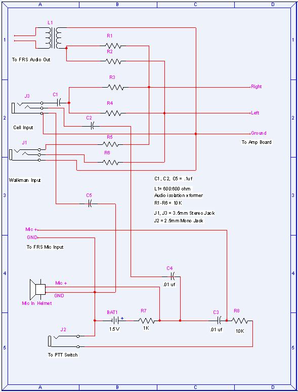
This should provide good wind noise rejection and a convenient mount for the mic in a full face helmet. The audio isolation transformer (L1) eliminates echo resulting from the fact that the FRS radio doesn`t share the same ground for both audio and mic.
Since the cell phone does share a ground, the transformer is unnecessary. If you wish to power this box and your other devices off of bike power, have a look at Bill Bowden`s Hobby Circuits, particullarly the Variable Voltage Regulator. This curcuit will alow you to transform bike power into a clean voltage source for your FRS, CD, amplifier, etc.
Cut the mic off the Chatterbox headset and solder on the WM55 mic. Insert the WM55 into the windsock and zip-tie the opening closed. Now the mic can be velcroed onto the helmet chin bar. Mount the headphone speakers and carefully tuck in all of the wires. You want to leave the plug where it`s not in the way, but easily accessable to attach the cord. Well, take the parts you`ve collected and follow the diagram below. The output of the amp and the input from the mic are connected to the hatterbox headset via a 6-pin mini din connector. Although it is not noted, I speced a 3. 5mm stereo jack for the "To FRS Audio Out" in hopes of getting a radio with the shared ground type headset plug like a cell phone.
It may be necessary to use two mono jacks, one for the FRS audio and one for the FRS mic. Either way, we ought to be able to make conversion plugs. After careful examination of the circuit around the condenser mic and consulting the WM55D datasheet. The mic can be driven by up to 10v and therefore can probably share the regulated voltage source used by the stereo amp.
I was initially confused by the arangement around the FRS mic, PTT switch, and the helmet mic. A standard consdenser mic hookup looks like this. You just drive the mic with 1. 5v-10v and pull the output off the positive lead with a capacitor. Now, the PTT switch is solely for the FRS radio and just throws the 10K resistor between the FRS mic and ground, putting a load on the mic circuit and sending a PTT signal to the radio. The helmet mic is always active and the cell phone is always listening, but the FRS only transmits when PTT is pressed.
I hate asymmetry. Let`s get that out in the open right now. Look at Paul`s original diagram. Do you see the symmetry Neither do I! Ok, the audio source, cell, and FRS all use an easy to get 1/8" stereo audio plug. Paul designed his orginal box for FRS/GMRS radios which take the two pin (1/8" mono - 3/32" mono) earphone/mic plugs. I`m redesigining it to use radio and cell phones with the 3/32" single pin headset standard. These share a ground between the mic and speaker so the FRS input plug wiring should look just like the cell input.
With the mic grounds and the speaker grounds being joined. If this becomes problematic, a separate mic and speaker ground can be achieved by linking the cell and FRS grounds to the mic ground via capacitors (0. 1uf). Paul may have had bunches of computer speakers lying around to canabalize, but I plan to build this low power stereo amp using a chip amplifier (National Semiconductor LM386-1).
I also found a 12mm stereo volume control audio potentiometer (Panasonic EVJ-C20F02A14) which I can use in the place of the two pots needed for the amp linked to above. This low part coun 🔗 External reference
Related Circuits
Wiring 2-Wire Intercom. According to Wikipedia, an intercom is a stand-alone electronic communications system intended for limited or private dialogue. A 2-wire intercom system is designed to facilitate communication over a limited distance, typically within buildings or residential areas. The...
The intercom schematic provides a reliable communication line and is straightforward to construct. The circuit consists of an amplifier, two switches, and two loudspeakers. If additional stations (speakers) are desired, more switches can be incorporated into the circuit. The...
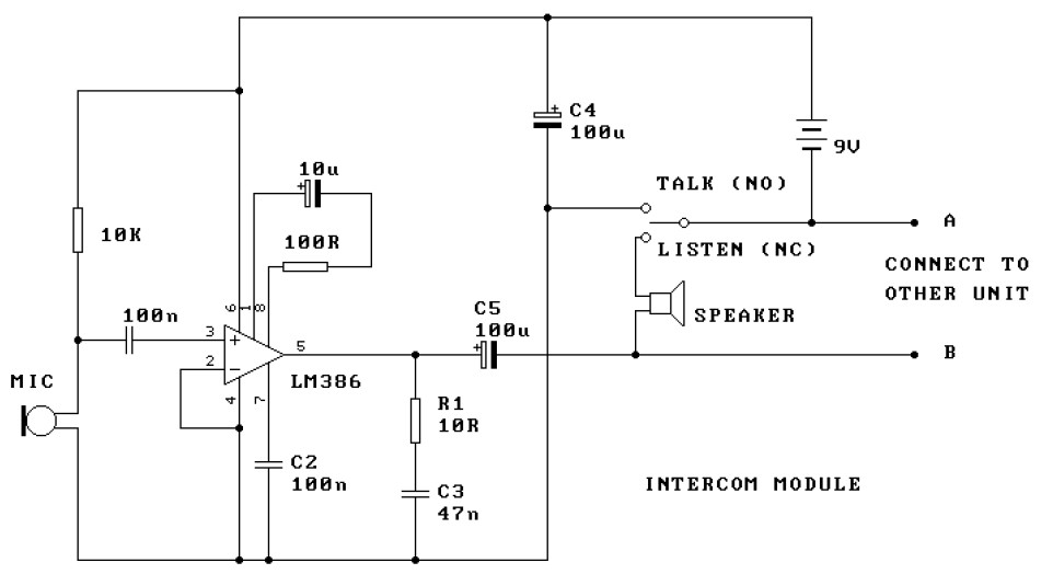
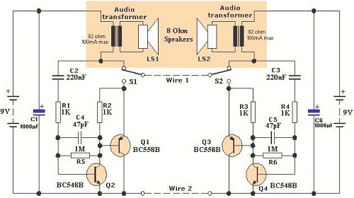
This is a two-station intercom system that operates using two wires connecting each intercom unit. Each unit is self-contained, equipped with its own battery, speaker, microphone, and amplifier circuit. An LM386 audio power amplifier is utilized, which is widely...
An 8-ohm speaker functions as both a microphone and an output device. The BC109C transistor operates in common base mode, providing substantial voltage gain while ensuring a low impedance input suitable for the speaker. Self DC biasing is implemented...
In this intercom schematic, an 8-ohm speaker is used as both a microphone and a listening speaker. A 10K potentiometer controls the volume, and the total gain can be adjusted. This intercom circuit utilizes an 8-ohm speaker in a dual...

This LM386 circuit is modified into a simple Doophone intercom that can be built. In this doorphone circuit, an 8-ohm speaker is utilized. The LM386 is a low-voltage audio power amplifier, commonly used in various audio applications, including intercom systems....