
Radio receiver GEOLOG circuit diagram
The receiver is designed to provide an intuitive user interface, particularly beneficial for nighttime operation. The scale bias lighting offers improved visibility, allowing users to easily read the scale even in low-light conditions. The fluorescent coating enhances this functionality by providing a glow that assists in the identification of scale markings.
The control layout is strategically organized for ease of access. The volume control knob (1) allows for quick adjustments to sound levels, while the tone control knob (2) enables the user to modify audio quality to their preference. The scale illumination button (3) is conveniently located for immediate activation, ensuring that users can illuminate the scale without distraction.
The band switch button (4) provides the capability to select different radio frequency bands, enhancing the versatility of the receiver. The telescopic antenna (5) contributes to improved signal reception, allowing users to access a broader range of radio stations. The tuning knob (6) is essential for fine-tuning to specific frequencies, ensuring clear audio output.
For audio output, the receiver is equipped with an earphone jack (8), which, when utilized, automatically disconnects the loudspeaker to prevent feedback and enhance listening quality. The external supply jack (7) allows for connection to an external power source, extending the operational time of the device. Additionally, the external antenna jack (9) and earthing jack (10) provide options for enhanced signal reception and grounding, respectively.
The lower cover (11) serves as a protective enclosure for the internal components, and proper battery installation is critical for the receiver's operation. Users must refer to the provided diagram (Fig. 3) to ensure correct battery orientation, as improper installation can lead to irreversible damage to the device. This careful design consideration ensures reliability and longevity for users, making the receiver a practical choice for both casual and dedicated radio enthusiasts.For convenience of use at night the receiver is provided with a scale bias lighting and the surface behind the scale has a fluorescent coating. To illuminate the scale depress button 3. Radio programs can be listened in over the earphone which is connected to jack 8. With the earphone connected the loudspeaker is switched off automatically. 1 - vo lume control knob; 2 - tone control knob; 3 - scale illumination button; 4 - band switch button; 5 - telescopic antenna; 6 -tuning knob; 7 - external supply jack; 8-earphone jack; 9 - external antenna Jack; 10 - earthing jack; 11 - lower cover. Put in or replace the battery in accordance with Fig. 3, paying special attention to the correct positioning of the cells. The receiver will be damaged, if the battery is reversed. 🔗 External reference
Related Circuits
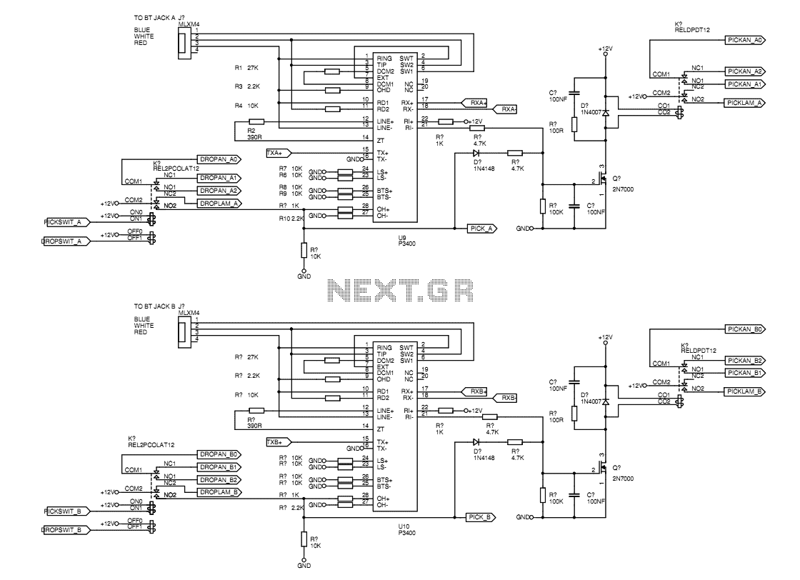
The hearts of the unit are the ETAL P3400 line modules available from Farnell. These modules mop up all of the line interface functions like ring detection, physical hybrid, on-off hook handling, etc. This means that the TBU as...
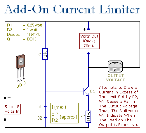
This circuit allows setting a limit on the maximum output current from a power supply unit (PSU). It is particularly useful when powering up a project for the first time or conducting a soak test. By establishing an upper...
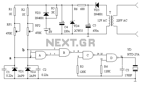
This circuit serves as an over-temperature alarm and cooling system utilizing CD4011 four NAND gate integrated circuits to monitor the oven's temperature. In the event of a thermostat circuit failure or power outage, if the internal temperature exceeds or...
The documentation and code cleaning for the Jaycar Thermor/BIOS branded wireless weather station receiver has been completed. The code is based on the Practical Arduino weather station receiver project. The process involved analyzing the RF signal from the weather...
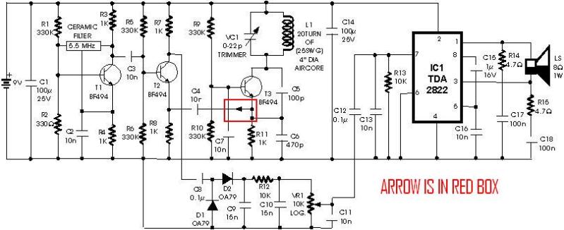
A schematic diagram for a metal detector has been found. The project does not need to be original and can be sourced from the internet. There are several questions regarding this schematic. One query pertains to a small arrow...
A complete GPS solution utilizing the MAXIM CMOS RF front-end receiver MAX2742 in conjunction with the SONY GPS baseband CXD2932 is presented. This GPS solution integrates two critical components: the MAX2742 RF front-end receiver and the SONY CXD2932 GPS baseband...
Warning: include(partials/cookie-banner.php): Failed to open stream: Permission denied in /var/www/html/nextgr/view-circuit.php on line 713
Warning: include(): Failed opening 'partials/cookie-banner.php' for inclusion (include_path='.:/usr/share/php') in /var/www/html/nextgr/view-circuit.php on line 713