
Bipolar stepper motor driver module circuit
The L297 stepping motor controller is an integrated circuit designed to facilitate the control of stepping motors, allowing precise operation in various applications. The controller is capable of handling both full-step and half-step driving modes, which can optimize torque and resolution based on the application's requirements. The CW/CCW pin configuration enables straightforward direction control, making it suitable for applications requiring bidirectional movement.
The CLOCK input is essential for speed regulation; by adjusting the frequency of the clock signal, the user can control the step rate of the motor, which directly influences the speed. The RESET functionality ensures that the system can return to a known state after power interruptions, which is critical for maintaining operational integrity in automated systems.
The ENABLE pin serves an important role in power management, allowing the motor phases to be disabled when not in use, thus conserving energy and preventing overheating. The reference voltage at VREF is crucial for setting the current through the motor coils, which affects the motor's performance characteristics such as torque and responsiveness.
The OSC pin's external RC network is vital for determining the chopping frequency of the drive circuit, which is essential for efficient operation of the stepping motor. The choice of resistor and capacitor values directly impacts the performance, and the specified minimum resistance helps prevent excessive current draw, ensuring safe operation.
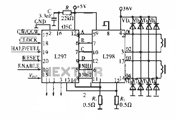
Overall, the L297 controller provides a robust solution for driving stepping motors, offering flexibility in speed, direction, and operational modes, making it an excellent choice for various applications in robotics, CNC machinery, and precision positioning systems.Circuit works: Figure shows a dedicated stepping motor controller L297 key pin, 17 feet (cw / ccw) is used to control the stepper motor rotation direction 18 feet (CLOCK) used to control the speed of the stepping motor speed ; 19 feet (HALF / FULL) for stepper motor full-step, half-step selection; 20 feet (rESET) is low, to the initial state when power is restored, ABCD = 0101; 10 feet (ENABLE) for the chip reset terminal when the terminal is low, ABCD = 0000, that is, each phase stepping motor is not energized in the workplace in order to manually adjust some tuning work location; 15 feet (VREF) as a reference voltage terminal of the voltage determines the step electric motive coil current is, Vvef = is Rs1 (Rs2), general Rs1 - Rs2 - 0.5 Omega; 16 feet (Osc) external RC value depends on the frequency of the chopping frequency of the chopper circuit is f = I / ( 0. 7R C), R must be greater than 10 k , 20 kHz shown in the figure is typical chopping frequency. Use this line to drive the following rated voltage 36 V, 2 A similar within all four lines, six lines of permanent magnet or hybrid stepping motor.
Related Circuits
A circuit diagram for an animal repeller is provided. The circuit has been developed but is not functioning as intended. Assistance is requested for troubleshooting. The animal repeller circuit typically employs ultrasonic sound waves to deter animals from specific areas....
The PIC16F84A digital thermometer circuit is constructed primarily using a temperature sensor along with various discrete components. The PIC16F84A microcontroller serves as the core processing unit of the digital thermometer circuit. It is equipped with an 8-bit architecture and supports...
The circuit presented is an integrated circuit (IC) controlled emergency light. Its key features include automatic activation of the light during mains failure and a battery charger equipped with overcharge protection. In the absence of mains power, relay RL2...
The electronic switch consists of the CK-4 type magnetic control switch and the components VT1, R1, and R2. When the bathroom door is closed, the permanent magnet ZT and the reed switch GA come into proximity, which separates the...
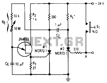
After one cycle of operation, SCR1 will be activated, resulting in a low voltage being applied to the UJT emitter circuit, which interrupts the tuning function. When pushbutton SI is pressed, or a positive pulse is applied at point...

This design has not been referred to as a GOLD detector, as that term is reserved for more complex devices capable of distinguishing gold from other metals. There is a significant difference between detecting gold and ordinary metals, known...
Warning: include(partials/cookie-banner.php): Failed to open stream: Permission denied in /var/www/html/nextgr/view-circuit.php on line 713
Warning: include(): Failed opening 'partials/cookie-banner.php' for inclusion (include_path='.:/usr/share/php') in /var/www/html/nextgr/view-circuit.php on line 713