
Intercom Circuit with a LM1458 opamp
The described circuit employs an operational amplifier (op-amp) configured as an audio amplifier, specifically tailored for intercom applications. The design utilizes an 8-ohm speaker functioning as a microphone, interfaced with the op-amp through a coupling capacitor of 0.1 µF. This capacitor plays a crucial role in filtering low-frequency signals, enhancing the overall audio response by attenuating undesirable low tones. Variations in capacitor values can be explored to optimize audio performance for different speaker types.
The voltage gain of the op-amp is set by the feedback resistor (1 MΩ) and the input resistor (1 kΩ), yielding a gain ratio of approximately 1000. The non-inverting input (pin 3) of the op-amp is biased to half the supply voltage (4.5 V) using a voltage divider formed by two 1 kΩ resistors. This biasing ensures that both the non-inverting and inverting inputs (pin 2) maintain equal voltage levels during linear operation.
The output stage includes a buffer transistor (2N3053) whose emitter voltage mirrors the inverting input voltage, also at 4.5 V. A minimal input change at the junction of the capacitor and resistor (2 mV) results in a voltage swing of approximately ±2 V at the transistor's emitter, leading to a current variation of about 60 mA through a 33-ohm emitter resistor. This current drives the output speaker, allowing for an estimated peak output power of 28 mW, calculated using the formula I²R.
To mitigate potential oscillations and ensure stable operation, a 100 Ω resistor and a 47 µF capacitor are incorporated to decouple the op-amp from the power supply. An additional 22 µF capacitor at the non-inverting input further enhances stability. While these components may be deemed unnecessary for low-power applications, their inclusion is prudent for maintaining circuit integrity and minimizing feedback.
The circuit operates from a 9 V power source, drawing roughly 1.2 W, which indicates a relatively low efficiency. Practical testing was conducted using two 4-inch speakers positioned a few feet apart to minimize feedback, with a small pocket transistor radio utilized as the audio source. This setup demonstrates the simplicity and effectiveness of the circuit for basic intercom functionality.The example below illustrates using an op-amp as an audio amplifier for a simple intercom. A small 8 ohm speaker is used as a microphone which is coupled to the op-amp input through a 0.1uF capacitor. The speaker is sensitive to low frequencies and the small value capacitor serves to attenuate the lower tones and produce a better overall response.
You can experiment with different value capacitors to improve the response for various speakers. The op-amp voltage gain is determined by the ratio of the feedback resistor to the series input resistor which is around one thousand in this case (1 Meg / 1K). The non-inverting input (pin 3) to the op-amp is biased at 50% of the supply voltage (4.5 volts) by a couple 1K resistors connected across the supply. Since both inputs will be equal when the op-amp is operating within it's linear range, the voltage at the inverting input (pin 2) and the emitter of the buffer transistor (2N3053) will also be 4.5 volts.
The voltage change at the emitter of the transistor will be around +/- 2 volts for a 2 millivolt change at the input (junction of 0.1 cap and 1K resistor) which produces a current change of about 2/33 = 60 mA through the 33 ohm emitter resistor and the speaker output. The peak output speaker power is about I^2 * R or .06 ^2 * 8 = 28 milliwatts. The 100 resistor and 47uF capacitor are used to isolate the op-amp from the power supply and reduce the possibility of oscillation.
An additional 22uF cap is used at the non-inverting input to further stabilize operation. These parts may not be needed in such a low power circuit but it's a good idea to decouple the power supply to avoid unwanted feedback. The circuit draws about 1.2 watts from a 9 volt source and is not very efficient but fairly simple to put together.
The circuit was tested using a couple 4 inch speakers located a few feet apart (to reduce feedback) and a small pocket transistor radio placed on top of the speaker/microphone as an audio source. 🔗 External reference
Related Circuits

This simple circuit indicates the status of a phone, including Line OK, Dialing, and Call Attended. It also features a locking mechanism to block outgoing calls while allowing incoming calls, preventing misuse of the telephone. The circuit requires only...
An LED flasher circuit can be constructed using a 555 integrated circuit (IC). The use of the 555 IC allows for greater flexibility in adjusting the flashing rate of the LED. This LED flasher circuit is similar to other...
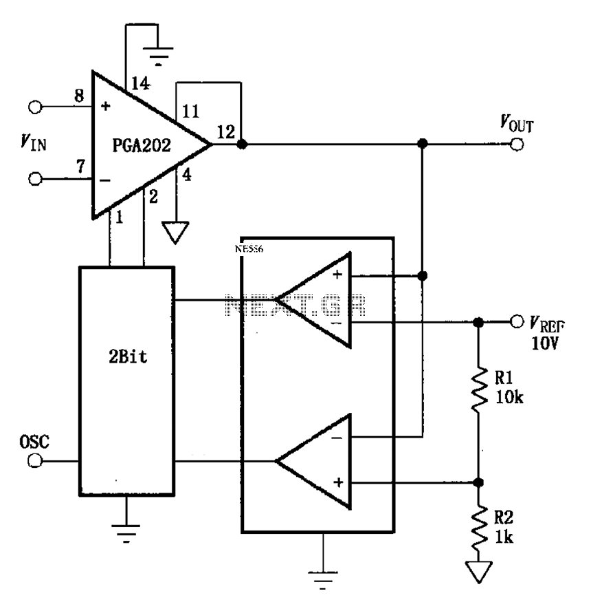
The automatic range switching circuit consists of PGA202, comparators, and counters, as illustrated in the figure. The comparator at the output compares VOUT with VREF. When VOUT exceeds 10V, the comparator generates a low signal, causing the up/down counter...
This Wien bridge oscillator is straightforward and, like all Wien oscillators, exhibits low distortion. The resonance frequency can be easily adjusted. The Wien bridge oscillator is a type of electronic oscillator that generates sine waves. It is based on the principle...

A simple 16-volt switching power supply circuit can be constructed using the provided diagram, which is based on the MAX668 constant-frequency, pulse-width modulating (PWM), current-mode DC-DC controller. This integrated circuit is designed for a wide range of DC-DC conversion...
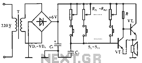
The circuit includes resistors Rp1 to Rp13, which serve dual purposes: they scale the resistance for the keyboard and function as timing resistors for the oscillator. Capacitor C2 acts as a wide discharge capacitor, while switches S1 to S13...
Warning: include(partials/cookie-banner.php): Failed to open stream: Permission denied in /var/www/html/nextgr/view-circuit.php on line 713
Warning: include(): Failed opening 'partials/cookie-banner.php' for inclusion (include_path='.:/usr/share/php') in /var/www/html/nextgr/view-circuit.php on line 713