
Telephone Status Indicator Circuit

This circuit design provides a straightforward solution for telephone line status indication and call management. The use of a minimal number of components enhances reliability and ease of assembly. The direct connection to the telephone line ensures that the circuit operates without the need for an external power source, making it suitable for various applications where power availability may be limited.
The circuit operates effectively by utilizing the voltage changes associated with the telephone line's On Hook and Off Hook states. In the On Hook state, the presence of approximately 48 volts is harnessed, while the transition to the Off Hook state reduces this voltage to around 12 volts, which is suitable for the operation of the LEDs and other components. Capacitor C1 plays a crucial role in protecting the LED indicators by limiting the voltage to a safe level, thus preventing potential damage.
The visual indicators—red and green LEDs—provide clear and immediate feedback regarding the status of the phone line. The red LED serves a dual purpose: it indicates that the line is operational when Off Hook and blinks during the dialing process, signaling that a call is being initiated. The green LED confirms that the call has been successfully established once the recipient answers.
The inclusion of a locking mechanism via a toggle switch enhances the functionality of the circuit by allowing the user to prevent unauthorized outgoing calls. This feature is particularly beneficial in environments where the telephone may be at risk of misuse. The option to replace the toggle switch with an electrical lock adds an extra layer of security, making the circuit adaptable to various user needs.
Overall, this circuit design exemplifies a practical approach to telephone line management, combining functionality, safety, and user-friendly features in a compact and efficient layout.This simple circuit tells you about the status of phone such as Line OK, Dialing and Call attended. It also has a lock facility to block outgoing calls keeping the incoming calls as usual. This prevents misuse of telephone. The circuit uses only a few components to do all these jobs. The circuit is directly connected to the telephone lines and no power supply is needed. In the On Hook state, the telephone lines have around 48 volts which reduces to 12 volts in Off Hook state. More over the line polarity changes during dialing and two way speech. Capacitors C1 reduce the line voltage to a safer level for the operation of LEDs. When the phone is Off Hook, Red LED lights to indicate that the lines are OK. When a call is dialed, Red LED blinks to indicate the dialing status. When the remote person attends the call, Green LED lights indicating that the call is attended. A simple Toggle switch is provided as Lock. It can be replaced with an electrical lock with key. When the switch is in Off position, outgoing calls will be blocked but the telephone receives incoming calls as usual.
🔗 External reference
Related Circuits

The Pyro Propeller Clock POV schematic is relatively straightforward. It consists of three primary components: the power supply utilizing a 7805 voltage regulator, the LED output control managed by a PIC18F252 microcontroller and a 74LS373 latch, and the 'home'...
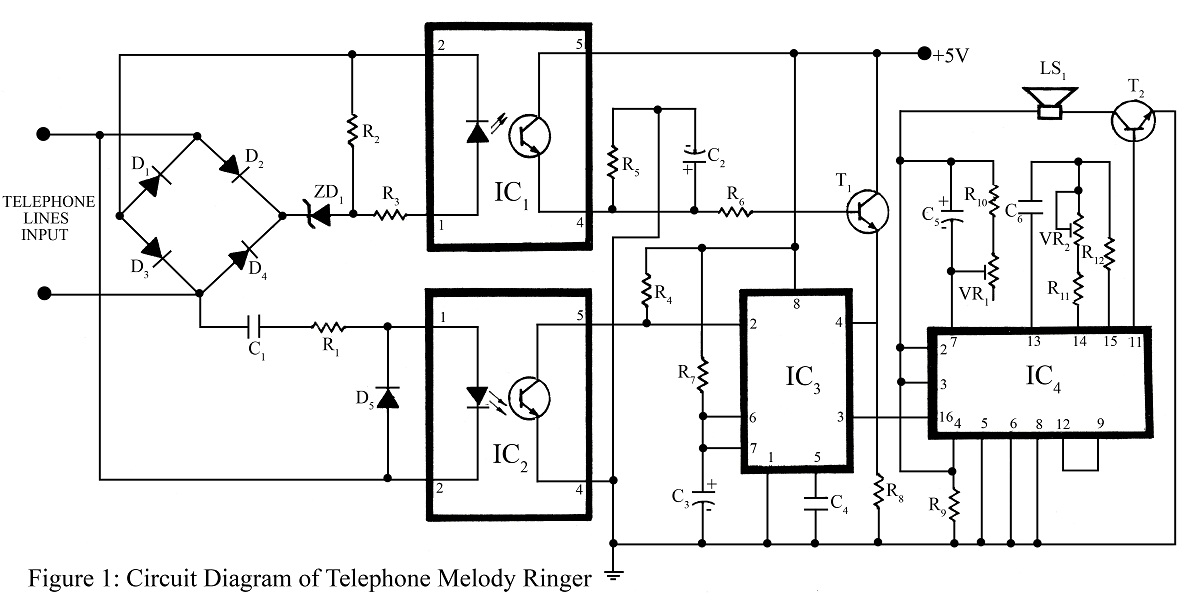
The telephone project described here is a telephone ringer that produces pleasant tunes when a call is received. The tunes generated by this telephone ringer are more melodious and soothing compared to those of traditional telephone instruments and piezo...
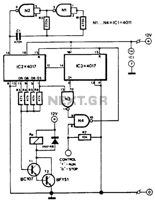
This circuit is designed for a small private telephone installation. The ringing tone sequence consists of 400 ms on, 200 ms off, 400 ms on, and 2 ms off. In the accompanying diagram, N1 and N2 create an oscillator...
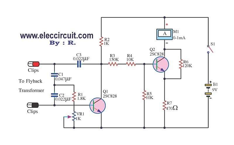
The circuit tests a flyback transformer used in televisions, and it is simple, easy, and inexpensive to construct. A friend who is a TV repairman provided this information. The circuit designed for testing a flyback transformer is essential for diagnosing...

This is a circuit design for a doorbell that produces a sound resembling that of a bird. The circuit is controlled by an NPN transistor. The operation begins when P1 is set to an experimental value, starting with approximately...
The IC1 is a 555 timer IC configured for astable operation, generating clock pulses that are fed to IC2 through a 10K resistor. IC2 is a 10-stage counter, with output 6 (pin 5) connected to RESET (pin 15), resulting...