
Interface Circuits

To create a reliable interface between an Amiga A1200 and a PC AT/ATX power supply and tower case, it is essential to design a circuit that effectively manages power requirements and signal compatibility. The Amiga A1200 typically operates on a 5V power supply, while AT/ATX power supplies provide multiple voltage outputs, including 3.3V, 5V, and 12V.
The circuit design should incorporate a power distribution board that connects the power supply outputs to the Amiga's power input. This board should include voltage regulators to ensure stable voltage levels are supplied to the Amiga. Additionally, decoupling capacitors must be placed near the power input of the Amiga to filter out noise and provide stable operation.
In terms of physical integration, the Amiga A1200 can be housed within a standard PC tower case. Proper mounting hardware should be used to secure the A1200 motherboard within the case, and appropriate cutouts must be made for ports and connectors. The power supply should be mounted securely, ensuring that all wiring is neatly organized to prevent interference and to facilitate airflow.
The circuit may also include a power switch that can control the power supply, allowing for easy operation of the Amiga A1200 from the front of the PC case. Additionally, LED indicators can be integrated to provide visual feedback on power status.
Overall, the project requires careful consideration of electrical specifications, physical layout, and user interface to ensure compatibility and functionality between the Amiga A1200 and the PC AT/ATX power supply and tower case.Building circuits to interface an Amiga A1200 to a PC AT/ATX power supply and tower case.. 🔗 External reference
Related Circuits
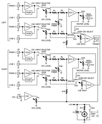
The mixer circuit features two line inputs and two microphone inputs, along with two line outputs. The microphone inputs are designed for low-impedance dynamic microphones with an impedance range of 200-1000 ohms. This simple mixer was specifically designed to...
Remove the 6 mm screw that secures the lower rear fairing cover. This cover is the black plastic piece to which the spark plug protectors are attached. Only the machine screw should be removed; do not detach the lower...
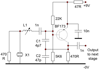
This circuit operates effectively from low frequencies up to at least 120 MHz using series resonant crystals in their fundamental or overtone mode. The output can be obtained from the feedback tap, a low impedance winding on L2, or...
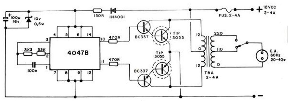
The converter transforms 12 VDC to 220 VAC, allowing for the conversion of 12 volts DC into 220 volts AC. The circuit diagram provided illustrates a simple converter circuit. This DC to AC converter can supply voltage for a...
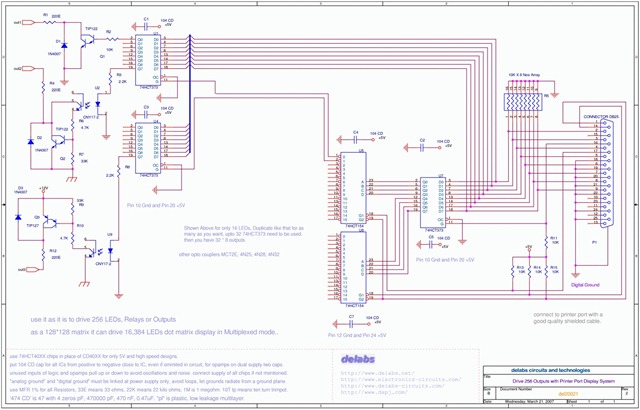
The following schematic illustrates the design of a Parallel Port Interface Circuit Diagram utilizing the 74HCT373. The 74HC/HCT373 are high-speed silicon-gate CMOS devices that are pin-compatible with low-power Schottky TTL (LSTTL). This parallel port interface circuit can drive 256...
This circuit is a digital panel meter (DPM) featuring an analog bar graph display and a 3.5-digit digital display. The ICL7107 is configured for 200mV input. The U4A operational amplifier (LF353) amplifies the 200mV full-scale input to the required...