
Interfacing ADAU1701 with AD1955

The ADAU1701 is a digital audio processor that integrates a range of functionalities, including digital signal processing and audio interfacing capabilities. When configuring the system, it is critical to ensure that the clock signals, MCLK and BCLK, are appropriately generated and utilized. MP11 serves as a versatile output, providing both MCLK and BCLK, which is essential for synchronizing audio data transmission between the ADAU1701 and the AD1955 DAC.
In typical applications, the MCLK is derived from a higher frequency source, such as a crystal oscillator or an active oscillator. The choice of using a buffered version of the oscillator output is recommended to ensure signal integrity and stability, particularly when interfacing with the AD1955, which operates at a higher voltage level. The ADG3304 is identified as a suitable component for level shifting between the 3.3V logic of the ADAU1701 and the 5V logic of the AD1955, ensuring that the signals are compatible and preventing potential damage to the components.
The frequency relationship between MCLK and BCLK is crucial for proper operation. The BCLK frequency is typically set at 64 times the sample rate (fs), while MCLK is set at 256 times fs. This configuration is essential for maintaining proper timing and synchronization in I2S audio data transmission. It is important to verify that the output impedance and drive strength of the ADAU1701 are adequate to drive the inputs of the ADG3304, which in turn will interface with the AD1955.
Finally, when configuring the system in SigmaStudio, the settings for MP11 should be adjusted according to the desired clocking scheme, ensuring that the BCLK output is correctly configured to meet the requirements of the AD1955. This comprehensive approach will facilitate successful audio data transmission and ensure optimal performance of the audio processing system.The ADAU1701 datasheet recommends on p18 that MP11 be used to derive MCLK. Now MP11 also serves the purpose of OUTPUT_BCLK when used for I2S. Therefore does this mean that I can connect MCLK and BCLK together 2. The ADAU1701 operates at 3V3 and AD1955 at 5V. Is the ADG3304 a good choice to perform the voltage level translation between the two at these frequencies 1) Are you using a crystal with the ADAU1701, or an active oscillator If you are using a crystal, I would recommend using a buffered version of OSCO to provide MCLK for the AD1955. If you are using an active oscillator, I would provide a second feed from it to the AD1955. You are correct that MP11 of the ADAU1701 should be used for BCLK; MCLK and BCLK will not be the same frequency, in most configurations.
BCLK will be 64 G— fs and MCLK will depend on your fs and register settings, usually 256 G— fs. 2) The ADG3304 would be a good choice for translating 3. 3 V serial audio into 5 V serial audio. 12. 288 MHz (for fs = 48 kHz) has a duty cycle of 82 nS; the switching characteristics of the ADG3304 will be able to handle this well. 1. I am using a 12. 28 MHz crystal - pretty much ditto configuration as the ADAU1701 I2C config schematic in the datasheet, so that makes it 256xfs since I am using fs=48kHz.
2. My primary intent is to use the AD1955 in the simplest possible config without a uC, so I am going by the default power-on parameters for the AD1955. if in this mode BCLK must be 64xfs, I conclude that the default hardware config in SigmaStudio must be altered for MP11 to "internal clock/4" for BCLK rather than "internal clock/16" which seems to be the default in SS.
drives the input of the ADG3304 channels should have an output impedance of less than or equal to 150 © and a minimum peak current driving capability of 36 mA. " This threw me. Is this correct and if so could it work directly with the ADAU1701`s outputs The BCLK output can be used as the MCLK output, but it`s probably worth trying this first on the evaluation board to make sure the drive strength is sufficient to drive two input pins on the DAC.
We do not spec the output impedance of the ADAU1701`s output drivers. I would expect, however, that the drivers are capable of providing sufficient drive strength to the ADG3304. On looking at the AD1955 datasheet page 14 it appears that in the default mode without a uC the BCLK and MCLK inputs on the AD1955 can probably not be tied together because the default MCLK mode in Table II is 256fs.
To send I2S from ADAU1701 to AD1955, with the AD1955 operating with SPI pins tied to DGND (no uC), do the following to the ADAU1701/SigmaStudio in the hardware configuration register control page: (ADAU1701 is operating at fs=48kHz and crystal of 256fs. ) 🔗 External reference
Related Circuits
The initial step often taken when learning about any microcontroller or embedded system is to make an LED blink. The circuit presented below illustrates the setup for interfacing an LED. Note: Due to the large dimensions of the circuit...
In the present day, a wide variety of sensors are available to measure almost anything. This tutorial will explore the fascinating world of sensors, starting with a very simple analog temperature sensor, the LM35. The process of interfacing it...
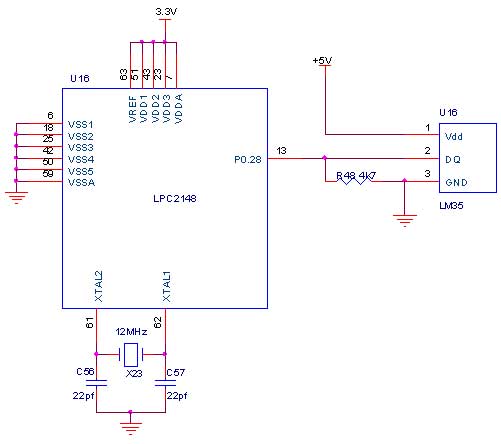
The LM35 series consists of precision integrated-circuit temperature sensors, with an output voltage that is linearly proportional to the temperature in degrees Celsius. The sensor's output can be converted to a digital signal, facilitating easy connection to a microcontroller....
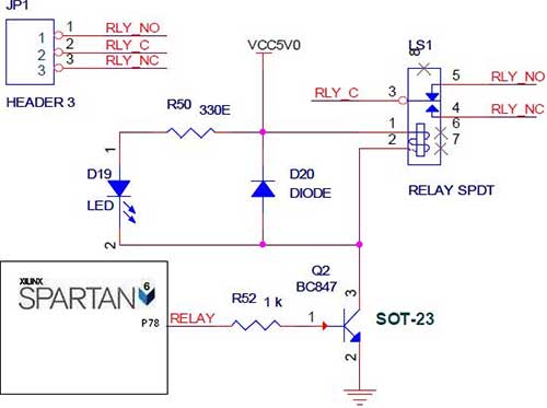
The Spartan-6 board features onboard 5V relay interfacing, as illustrated in the accompanying figure. The ULN2803 serves as a driver for the FPGA I/O lines, with the driver's outputs connected to the relay modules. A PTB connector is provided...
The EN line is referred to as 'Enable'. This control line is utilized to indicate to the LCD that data is being sent. To transmit data to the LCD, the program must ensure that this line is low (0),...

An 8051 program must interact with external devices that facilitate communication with users. One of the most prevalent devices connected to an 8051 microcontroller is an LCD display. Common types of LCDs used with the 8051 include 16x2 and...