
Interfacing LM35 Temperature Sensor with PIC Microcontroller

The LM35 temperature sensor is a precision integrated-circuit temperature sensor that provides an output voltage linearly proportional to the Celsius temperature. It operates within a temperature range of -55°C to +150°C and has an output scale factor of 10 mV/°C. This means that at 0°C, the output voltage will be 0V, and at 25°C, it will generate an output of 250 mV.
To interface the LM35 with a PIC microcontroller, the following steps are typically involved:
1. **Circuit Design**: The LM35 sensor is connected to an analog input pin of the PIC microcontroller. It requires a power supply, usually +5V, which can be provided by the microcontroller. A bypass capacitor may be added to the power supply line to filter out noise.
2. **Analog-to-Digital Conversion (ADC)**: The PIC microcontroller will convert the analog voltage output from the LM35 into a digital value using its built-in ADC. The ADC resolution will determine the precision of the temperature readings. For example, an 8-bit ADC will provide values ranging from 0 to 255, while a 10-bit ADC will provide values from 0 to 1023.
3. **Temperature Calculation**: Once the ADC conversion is complete, the digital value must be translated back into a temperature reading. This can be accomplished using the formula:
\[
\text{Temperature (°C)} = \frac{\text{ADC Value} \times 5V}{1023} \times 100
\]
This equation assumes a 10-bit ADC with a reference voltage of 5V.
4. **Displaying Results**: The results can be displayed on a 16x2 LCD module. The PIC microcontroller will send the calculated temperature value to the LCD for visualization. This typically involves initializing the LCD, setting the cursor position, and sending the temperature data formatted as a string.
5. **Programming**: The microcontroller can be programmed using languages such as C or assembly. The code will include initialization routines for the ADC and LCD, a loop for continuous temperature reading, and the conversion and display logic.
This basic setup provides a foundation for various applications, including environmental monitoring, HVAC systems, and educational projects, showcasing the versatility and importance of temperature sensors in electronics.In present day, variety good sensors are available to measure almost anything. In this tutorial will explore the wonderful world of sensors, starting with a very simple analog temperature sensor LM35. We will learn how to interface it with PIC MCU and display the result in common 16x2 lcd module.. 🔗 External reference
Related Circuits

This preamplifier offers a loading ratio of better than -70 dB (referenced to a 10-ohm reluctance phono cartridge) and accepts millivolt input at 1 kHz. It has a dynamic range of approximately 35 dB of gain at 1 kHz...
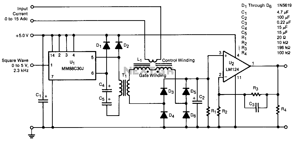
A transducer senses direct current magnetically, providing isolation between the input and the output. The detecting and isolating element is a saturable reactor, through which the input current to be measured passes via a one-turn control coil. The transducer...
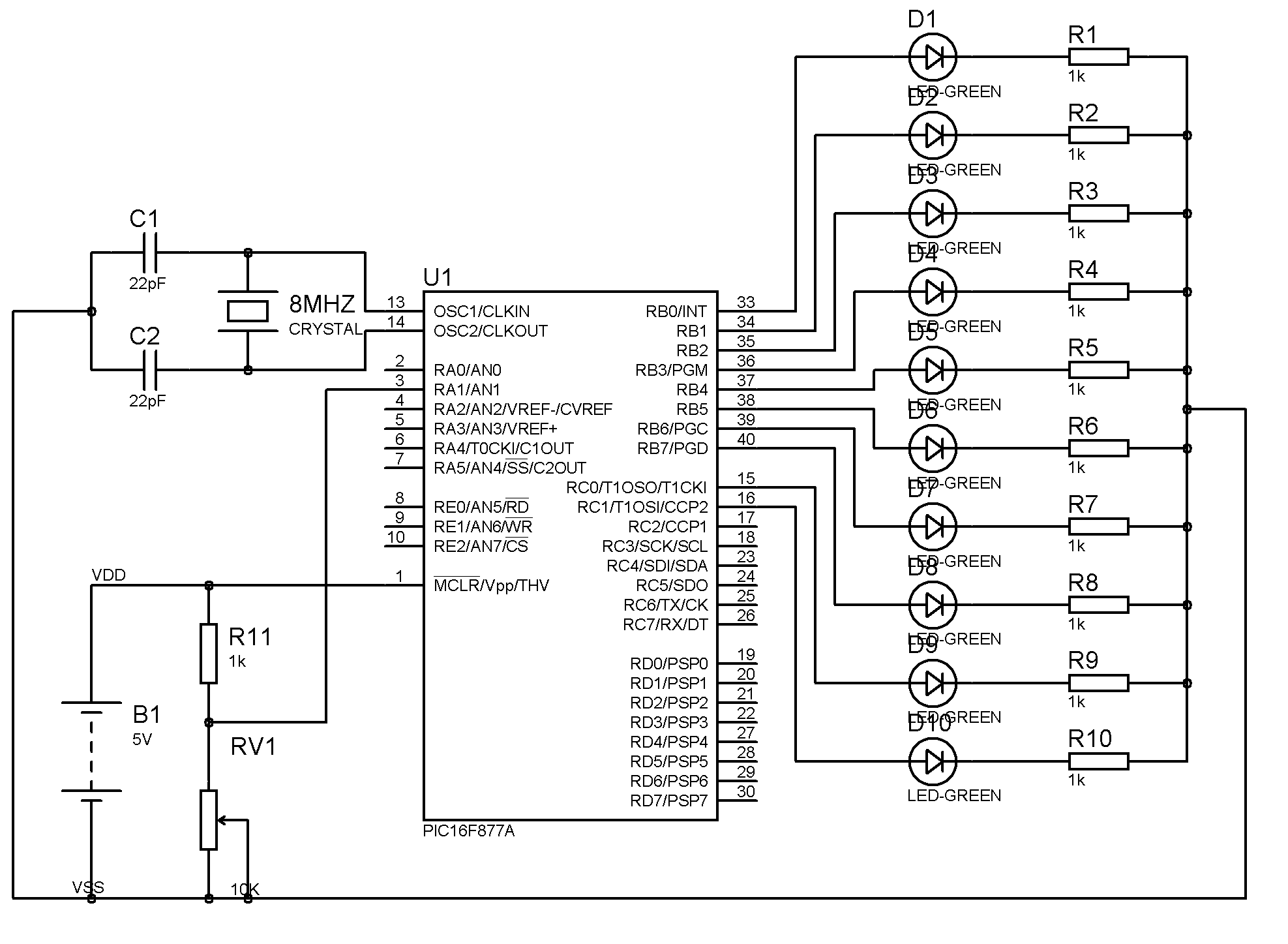
The program utilizes the internal 4 MHz oscillator of the PIC16F628 microcontroller in a two-input alarm circuit. The two-input alarm circuit designed with the PIC16F628 microcontroller leverages the internal 4 MHz oscillator to provide a stable clock signal for operation....
The result displayed on the LCD is incorrect; the thermometer shows a reading of 414 degrees instead of the actual room temperature. Assistance is needed to determine whether the issue lies within the hex file or the sensor itself....

This is a water sensor circuit design based on a Conductive Liquid Level Sensor. This single-chip circuit is compact and simple. It is an AC-excited fluid level sensor, which uses alternating current to provide biasing for the sensor probe,...
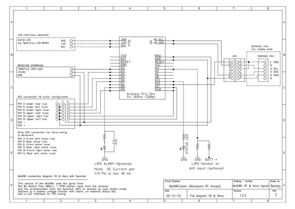
This is a video showcasing a test flight of the Quad Rotor Observer (QRO) v8, which is equipped with the FCWii board, Wii Motion Plus gyroscopes, and Nunchuk accelerometers. The Quad Rotor Observer (QRO) v8 is an advanced quadcopter designed...