
Interfacing to Sony Cameras

The circuit design for the intercom system involves several key components that work together to facilitate effective communication between the camera operator and the production team. The LM386 integrated circuit serves as the core amplification element, providing a reliable gain of 20 dB, which is crucial for ensuring that the audio signal transmitted to the headset is sufficiently strong for clear communication. The inclusion of a potentiometer allows for user-friendly volume control, enabling the camera operator to tailor the audio level to their preference in real-time, enhancing usability during operation.
For the microphone signal, the design incorporates a second potentiometer dedicated to attenuation. This component is set during the installation phase, ensuring that the microphone signal is at an optimal level for transmission without requiring further adjustments. The use of a screwdriver-adjusted potentiometer emphasizes the need for a stable and consistent microphone level, preventing accidental changes during operation, which could disrupt communication.
Furthermore, the microphone mute switch is a critical feature that allows the camera operator to quickly silence the microphone when necessary, providing an essential function for maintaining privacy and control over audio transmission. This switch is strategically placed for easy access, allowing the operator to engage or disengage the microphone without distraction.
Overall, the integration of these components into a compact circuit board within the camera ensures that the intercom system operates efficiently, providing reliable audio communication while accommodating the specific needs of the camera operator. The design is based on established engineering principles and manufacturer guidelines, ensuring both functionality and ease of use in a professional environment.The Clearcom type intercom bus runs at a significantly lower level than the Sony bus, the signal to the camera operator`s headset must be boosted and the signal from the camera operator`s microphone must be attenuated. To do this a very small circuit board is added to the camera containing this circuitry. The earphone level is boosted wit h an LM386 integrated circuit which has a fixed gain of 20 dB. A potentiometer is provided to allow the camera operator to adjust the earphone volume. The rest of the circuit is derived from the manufacturer`s data sheet. Another potentionmeter is provided to attenuate the microphone level. This is an internal screwdriver adjust pot since it is adjusted once at installation and not changed by the camera operator. Also provided is a microphone mute switch. 🔗 External reference
Related Circuits
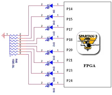
The Spartan-3 board features eight LEDs connected to FPGA I/O pins, with the cathode of each LED connected to ground through a 330-ohm resistor. To illuminate a specific LED, the corresponding FPGA control signal must be driven to a...
This circuit was designed for digital cameras, which are known to have significant power consumption. For instance, the Minolta E223 camera requires approximately 800 mA. In practice, this demand can be met using a mains power supply or high-capacity...
You may find that there are too few, if your power is very noisy (as can happen in a car environment) it may help to place a 0.1uF and/or 10uF capacitor before and/or after the voltage regulator. At the...
This article describes three options for interfacing the DS1859 to the MAX3735. It includes a new technique using an operational amplifier that provides a linear transfer function, which can be adjusted for any arbitrary current range. All of these...
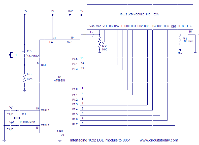
Interfacing a 16x2 alphanumeric LCD module with the AT89S51 microcontroller. The circuit diagram, theory, and program are included. JHD162 LCD module pinout and commands are provided. The integration of a 16x2 alphanumeric LCD module with the AT89S51 microcontroller involves several...
This article outlines a reliable, straightforward, and universal method for interfacing Motorola mobile radios from the MaxTrac, Radius, and GM300 series with common repeater controllers. The information provided is also relevant for radio interfaces used in IRLP or EchoLink...