
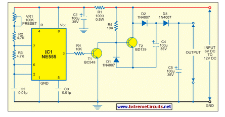
Low-Power Voltage Doubler (Booster)
Miniature electronic devices, which include a wide range of applications from portable gadgets to remote sensors, typically rely on battery power for operation. However, many of these devices necessitate voltages that exceed the nominal levels provided by standard batteries. This requirement can be addressed through various methods, such as using a boost converter circuit.
A boost converter is a DC-DC converter that steps up the input voltage to a higher output voltage, making it suitable for powering devices that require more energy than is available from the battery source. The basic operation of a boost converter involves an inductor, a switch (usually a transistor), a diode, and a capacitor.
When the switch is closed, current flows through the inductor, storing energy in its magnetic field. Once the switch opens, the energy stored in the inductor is released, causing the voltage to increase due to the collapsing magnetic field. The diode prevents the current from flowing back into the switch, directing it instead to the output capacitor, which smooths out the voltage to provide a stable output.
The design of the boost converter must consider factors such as the input voltage range, desired output voltage, load current, and efficiency. Additionally, feedback control mechanisms are often implemented to regulate the output voltage, ensuring that it remains stable despite variations in load or input voltage.
In summary, the integration of a boost converter into miniature electronic devices allows them to efficiently utilize battery power while meeting the higher voltage requirements necessary for optimal performance. This capability is pivotal in extending the functionality and longevity of portable electronic applications.All miniature electronic devices operate off batteries. Some of them need higher than the standard battery voltages to operate efficiently. If the battery.. 🔗 External reference
Related Circuits
This circuit will provide an indication whenever the input voltage differs from two defined limits, V1 and V2. The supply voltage, Vcc must be higher than the highest input voltage by at least 2 volts. One application here is...
This circuit diagram indicates when the input voltage deviates from two defined limits, V1 and V2. The limits are adjustable, and the circuit is designed to trigger the adjustable window. The supply voltage, Vcc, must be at least 2...

This is a Variable Voltage Regulator Circuit built using the LM317T integrated circuit (IC). The LM317T is an adjustable three-terminal positive voltage regulator capable of supplying more than 1.5 amps over an output range of 1.25 to 37 volts....
A distribution substation is defined by the apparent power of the transformer and its configuration, which can be aerial, terrestrial, or underground. A distribution substation plays a critical role in the electrical power distribution network. It serves as a point where...
As Ron suggests, controlling the output voltage from a regulator can be made variable in three ways. Using a fixed reference zener diode to increase the output by the value of the zener. A variable resistor for variable output,...
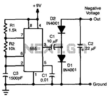
By utilizing a 555 timer to produce a square wave and employing a voltage-doubling technique on the output, a negative voltage that is nearly equivalent to the positive supply can be achieved. The available current ranges from 20 to...