
Interlock and connect DC DC converter scheme in parallel
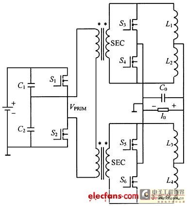
The schematic circuit diagram that the current-doubling commutates the high-current DC-DC converter of undervoltage is shown as in Fig. 1, primary side adopts the structure of symmetrical semi-bridge, secondaly side adopts the current-doubling to commutate the structure, SR1 must end when S1 turns on, L1 charges; SR2 must end when S2 turns on, L2 charges, so filtering inductive current will transplant on the Filtering capacitance and superpose. Fig. 2 provides the control strategy of the switch. Can be found out through the above-mentioned analysis, the current-doubling commutates 2 pieces of filtering inductive current of structural secondaly side to superpose on the Filtering capacitance each other, thus make the output current ripple quite small.
Synchronous rectifier in the structure drive, deal with according to extra signal, make it become it very much complicated not to control, but simple to use in this kind of semi-bridge topological structure of current-doubling since the driving means is very difficult, because in the structure, fetch appropriate the intersection of point and driving signal in synchronous rectifier in circuit directly, , for zero hour, synchronous rectifier will end as the driving signal within Dead Time. In order to use in the semi-bridge topological structure of current-doubling from the driving means, must use the auxiliary winding.
Take single semi-bridge topological structure of current-doubling as examples, see Fig. 3, VSEC is the voltage of secondaly side of the voltage transformer, Vgs for driving voltage of synchronous rectifier that obtain by auxiliary winding, can find out even during the time of the inert zone, the driving voltage of the synchronous rectifier can not be zero either, guarantee it from the application of the driving means in this kind of topological structure. In addition, because MOSFET turns on pressure drop and increases in case of heavy current, thus will produce the greater feed-through to loss, for this reason should adopt a plurality of MOSFET to connect the method in parallel to reduce lossing.
In sum, it has very good characteristics that the current-doubling commutates the high-current DC-DC converter of undervoltage, introduce and mixed with connecting technology in parallel on this basis, form a kind of new structure, called and connected the high-current DC-DC converter of undervoltage in parallel, can further reduce the output current ripple. Fig. 4 interlocks and connects the schematic circuit diagram of the high-current DC-DC converter of undervoltage commutate and interlock to connect in parallel for the example with simplest 2 pieces of current-doubling in parallel.
The advantage of this kind of topological structure maximum is the structure reduction of the primary side of the voltage transformer at first, it becomes very simple to control. Secondly, the realization of this method must adopt the synchronous rectifying circuit, because interlock the realization of the parallel circuit require upper and lower electric potential of secondary of voltage transformer to take turns in order that, there is one as the positive potential within a time quantum, the others are all zero potential.
But in this kind of topological structure, because the primary sides of 2 voltage transformers connect in series together, and the secondary is parallel, so f 🔗 External reference
Related Circuits
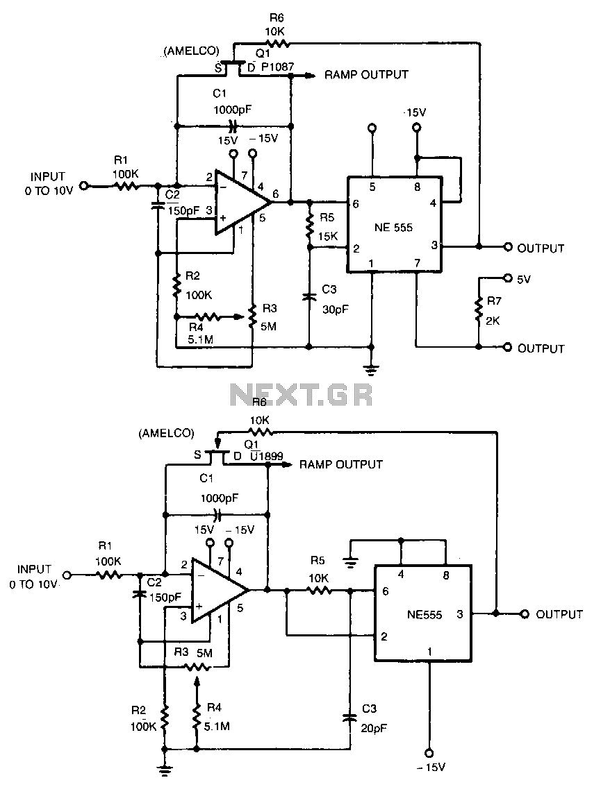
This linear voltage-to-frequency converter achieves good linearity over the range of 0 to -10 V. Its mirror image provides the same linearity over the range of 0 to +10 V; however, it is not compatible with DTL or TTL. The...
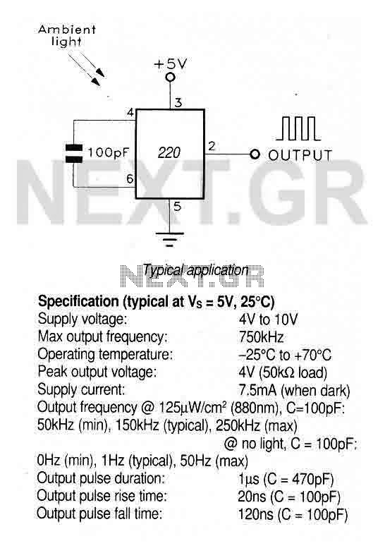
A large area photodiode and current-to-frequency converter integrated into a clear plastic 8-pin DIL package. The output generates a pulse train whose frequency is directly proportional to the light intensity. It is CMOS compatible (a 3.3kΩ pulldown resistor is...
The technology of range finding is extensively employed in civil and industrial fields, such as measurement, medical flaw detection, and car anti-collision systems, due to the relatively lower speed of ultrasonic waves compared to the speed of light. This...
This project is a VGA-to-Scope converter that utilizes composite video signals instead of VGA signals to display on an oscilloscope. The design has been simplified by removing op-amp buffers and inverters. A simple 1 Megohm potentiometer is used to...
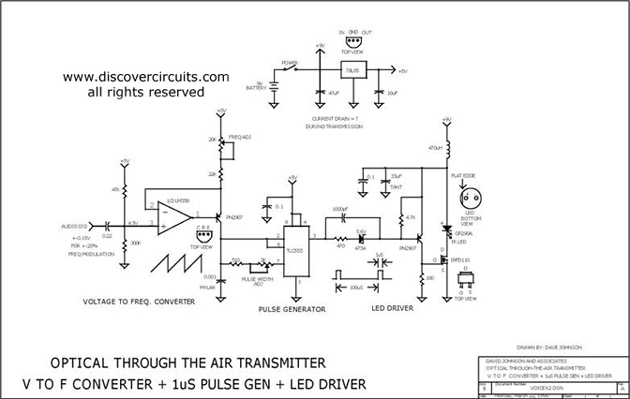
This circuit receives the signal from the amplifier and emits powerful 1μs infrared light pulses from a low-cost LED, which are frequency modulated by the audio information. The 10kHz center frequency of the pulse stream is sufficiently low, allowing...
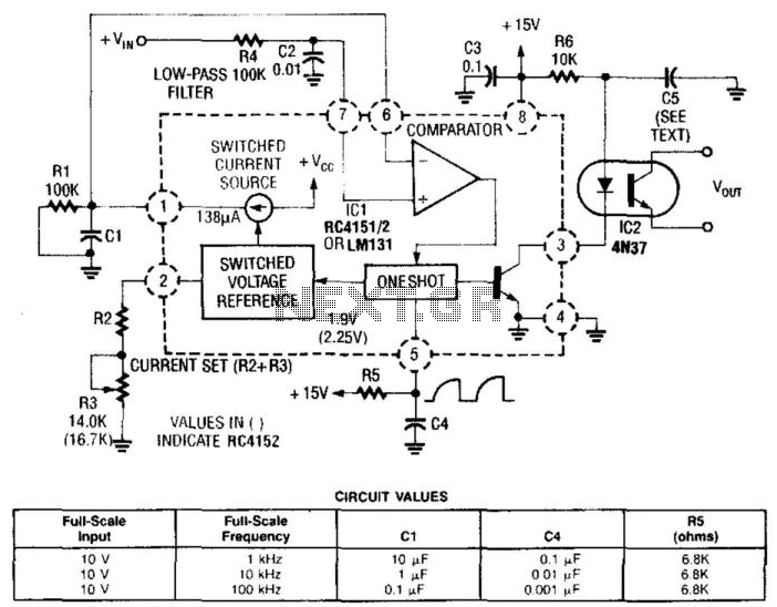
In this circuit, a Raytheon RC4151 or National LM131 is utilized alongside an optocoupler for applications where input-to-output isolation is desirable. Circuit values are indicated in the figure for various applications. The circuit employs a Raytheon RC4151 or National LM131,...
Warning: include(partials/cookie-banner.php): Failed to open stream: Permission denied in /var/www/html/nextgr/view-circuit.php on line 713
Warning: include(): Failed opening 'partials/cookie-banner.php' for inclusion (include_path='.:/usr/share/php') in /var/www/html/nextgr/view-circuit.php on line 713