
TV To Scope Converter
This VGA-to-Scope converter circuit effectively transforms composite video signals into a format suitable for display on an oscilloscope. The core of the circuit is based on a simplified design that eliminates unnecessary components, making it easier to assemble and use. The use of a 1 Megohm potentiometer for charging the capacitor introduces a nonlinear sawtooth waveform, which is a critical aspect of the oscilloscope's display characteristics.
The LM1881 chip plays a vital role in extracting synchronization signals from the composite video input. It generates vertical and horizontal synchronization signals necessary for the oscilloscope's operation. The vertical sync signal on pin 3 is utilized to drive the vertical oscillator, while the composite sync on pin 1 is used for the horizontal oscillator. This separation allows for accurate display of the incoming video signal on the oscilloscope.
The circuit also incorporates a 555 timer, which operates in an astable mode, providing a continuous sawtooth waveform necessary for raster generation. The feedback loop established from the output back to the trigger input enhances the circuit's stability, allowing it to generate a raster even in the absence of a video signal. This feature significantly reduces the risks associated with operating the oscilloscope without a video source, as it prevents the appearance of a static dot that could damage the CRT.
Furthermore, the inclusion of a 2N3906 transistor improves the linearity of the sawtooth output, enhancing the quality of the display. The synchronization process is facilitated by feeding the sync signal into the trigger input, which resets the 555 timer whenever a change in the sync signal occurs. This arrangement ensures that the oscilloscope remains synchronized with the incoming video signal, maintaining the integrity of the displayed waveform.
In summary, this VGA-to-Scope converter circuit is a practical solution for visualizing composite video signals on an oscilloscope. It combines simplicity and functionality, making it an effective tool for hobbyists and engineers alike. The careful consideration of component selection and circuit design contributes to a reliable and efficient conversion process, enabling users to explore and analyze video signals with ease.This project takes after the VGA-to-Scope converter by using composite video rather than VGA signals to create a display on an oscilloscope. The circuitry in the VGA-to-Scope converter has been greatly simplified; op-amp buffers and inverters were eliminated.
The continuous current supply to charge up the capacitor linearly (the 3906 PNP transisto r and associated resistors) was replaced with a simple 1Meg pot from 5V to charge up the capacitor, albeit creating a nonlinear sawtooth. When the pot is set just right, the capacitor will charge up at the correct rate and the trigger signal causes the 555 to discharge the capacitor for synchronization.
Below is the schematic. A LM1881 is used to do all the grunt work of separating the sync signals from the composite video. The chip provides the vertical sync on pin 3 for the vertical oscillator, and composite sync on pin 1 for the horizontal oscillator. The intensity signal comes from the composite video signal itself, but is negative. I didn`t really mind since this circuit took only 10-15 minutes to slap together. If an inverter is preferred to make the video "positive" then here is a schematic for the inverter below as taken from the VGA-Scope converter.
This circuit includes another 555 to generate the negative supply rail for the op-amps. CAUTION: The oscilloscope must have a X, Y, and Z axis, good gain, and X/Y inverters for this converter to be useful. Second, the video MUST be connected before you turn up the brightness of the oscilloscope. Without the video signal connected, the sweep generators are not operating due to the absence of sync signals so a dot appears on the CRT, which can burn the phosphor.
Make sure you have a raster before you turn up the brightness. The same goes for shutting down, turn down the brightness of the oscilloscope before you shut down the video source and/or converter. This converter is not as robust as the VGA-to-Scope converter so every time the circuit is powered up, the oscillators probably need readjustingso consider the 1Meg pots to be vertical and horizontal hold controls.
Among the improvements on version 1 includes the use of the 2N3906 and associated resistors for improved linearity of the sawtooth output. More importantly, a loop is introduced in the circuit from the output to the trigger input to allow the 555 timers to operate in astable (free running) mode.
The advantage is that a raster will be present in the absence of a video signal so one does not have to worry about all the precautions with the oscilloscope before and after using the converter. Below is a schematic of the slightly revised converter. The 555 works by allowing the capacitor to charge until the voltage reaches a certain threshold voltage that triggers the 555 to quickly discharge the capacitor then the process starts again with the capacitor charging up again.
The frequency is determined by the rate of the charge and is synchronized like a phase-locked loop. Synchronization is achieved simply by feeding the sync signal into the trigger input via a capacitor to create a crude AND gate that forces the 555 to reset whenever there is a voltage change in the sync signal. When the sync signal is absent, the 555 continues to free run although at a different frequency due to impedance changes on the trigger input with an absent sync signal.
Of course a simple converter can be done with tubes and has been done plenty times in the past when "hollow-state" was the only choice. I was inspired to build a converter after a fellow hobbyist created a converter based on a simple tube TV monitor schematic I had in the temporary folder.
The circuit minus the CRT circuitry is presented below. The 6AU6 tubes are used in a classic phantastron circuit that generates astable (free running) sawtooth waves. By providing a sync pulse to the phantastron circuit, a phase-locked loop can be achieved to create a synchronized sawtoo
🔗 External reference
Related Circuits
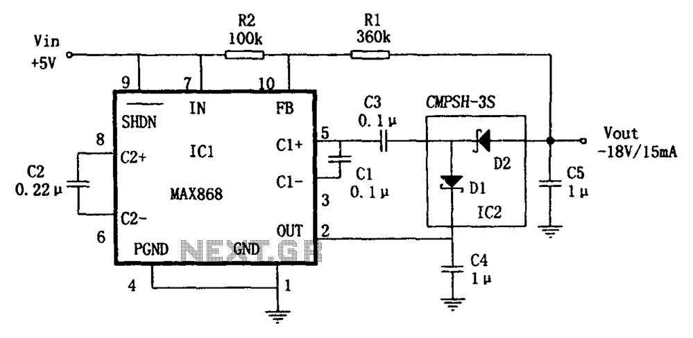
The circuit utilizes the IC1 MAX868 and CMPSH-3S to create a quadruple voltage DC/DC converter power supply. The IC1 MAX868 is an inverting charge pump regulator integrated circuit that can generate an output voltage of up to -2VIN, with...
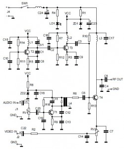
This is the circuit diagram of an audio/video modulator. The circuit converts audio and video signals into a UHF TV signal. It is designed to connect a video signal originating from a camera or other video source to a...
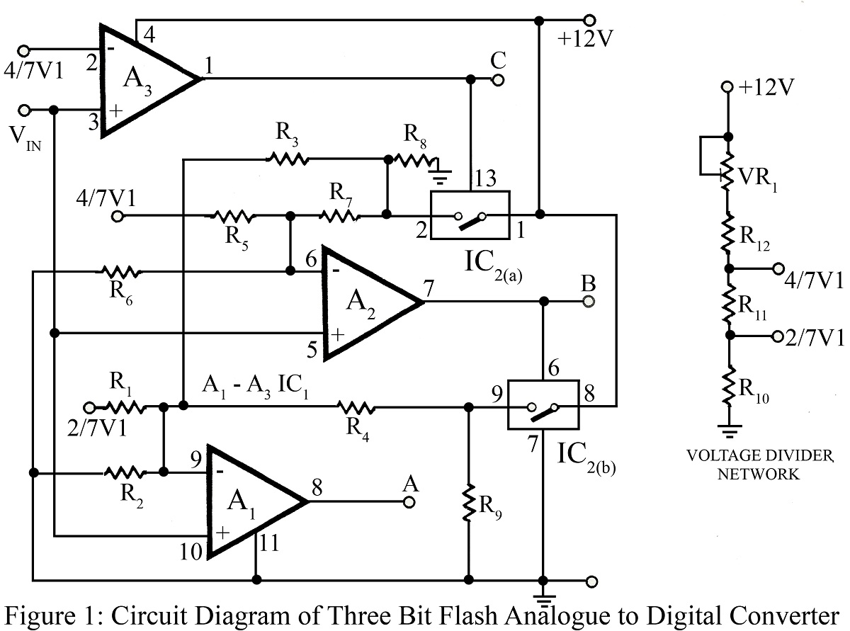
The flash type converter is the simplest and fastest type of analog-to-digital converter. The entire digital output word is available immediately after the propagation delay time of the comparators and the encoding logic gates. A typical conversion time for...
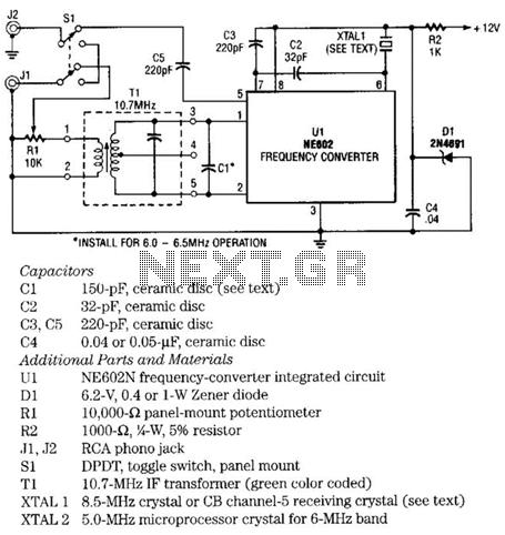
The NE602 chip, U1, contains oscillator and mixer stages. The mixer combines the oscillator signal with the input RF signal to produce signals whose frequencies are the sum and difference of the input frequencies. For example, an 8.5-MHz oscillator...
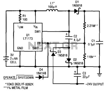
This circuit utilizes a Linear Technology LT1073 to function as a -24 V converter. The power supply can consist of two AA cells (3 V) or a 5 V source. The circuit is capable of delivering a current of...

This design circuit is a tachometer circuit based on the LM2907 integrated circuit, which can provide zero-crossing data to a digital system. At each zero crossing of the input signal, the charge pump alters the state of capacitor C1...