
The NE555 FM modulation circuit

The NE555 timer is a versatile integrated circuit commonly used for generating precise timing and oscillation in various applications. In this FM modulation circuit, the NE555 operates in astable mode, where it generates a continuous square wave output. The frequency of this oscillation is influenced by the values of R5 and C2, which form a timing network. The frequency range may be limited due to the component values selected, which can be adjusted to optimize performance.
The transistors VT1 and VT2 are configured in a current Miller circuit arrangement. This configuration is essential for creating a feedback loop that enhances the charging current within the circuit. The charging current is crucial for modulating the frequency of the output signal, and its magnitude is controlled by the resistors R2 and RP1. Adjusting these resistors allows for fine-tuning of the current flow, thereby impacting the modulation depth and overall performance of the circuit.
The low-frequency response of this circuit can be critical for applications requiring audio modulation or signal processing. The design considerations should include the selection of appropriate component values to achieve the desired frequency range and modulation characteristics. Additionally, the stability of the circuit under varying load conditions should be analyzed to ensure reliable operation. Overall, the NE555 FM modulation circuit presents a practical solution for generating modulated signals in electronic applications.In the figure is the NE555 FM modulation circuit. In the figure, NE555 7-pin is connected with a FM modulation circuit which is composed with R5 and C2, but the frequency range is kind of small. VT1 and VT2 form a current Miller circuit, which generates a charging current in the charging circuit, the current magnitude is decided by R2 and RP1.
The low-freque.. 🔗 External reference
Related Circuits
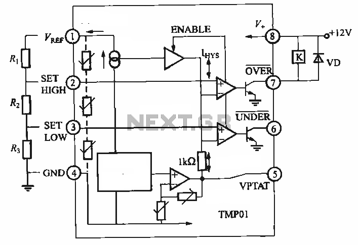
TMP01 is a temperature sensor that features a programmable temperature controller, an integrated reference voltage source, a current source, a voltage comparator, and an amplifier circuit. The internal circuit function block diagram and basic application circuit are provided. The key...
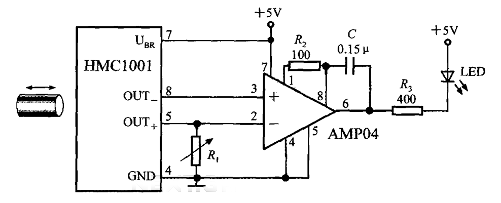
The circuit depicted in the figure includes the HMC1001 magnetic sensor, an operational amplifier (AMP04), and a light-emitting diode (LED), forming a proximity switch circuit. In this application, the operational amplifier functions as a comparator. When a magnet, approximately...
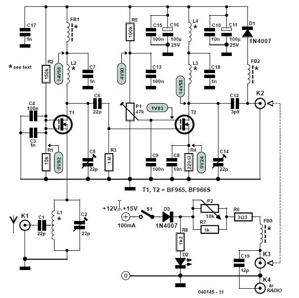
This high-performance two-stage antenna amplifier for the VHF FM broadcast band, when paired with a quality directional antenna, allows for the reception of distant (DX) stations. It significantly enhances the reception of FM signals that may otherwise be considered...
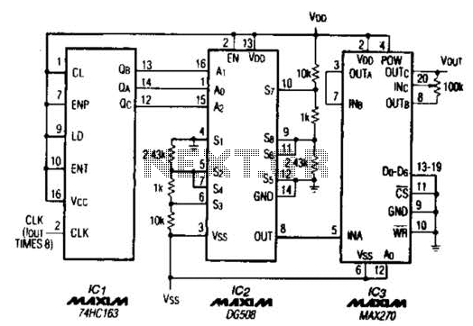
A TTL counter, an 8-channel analog multiplexer, and a fourth-order low-pass filter can generate sine waves ranging from 10 kHz to 25 kHz with a total harmonic distortion (THD) better than -80 dB. The circuit employs two cascaded second-order,...

The Switchgate is a simple dual gate circuit based on a 556 timer configured in monostable mode, featuring a trigger input that activates two switches. The outputs of the monostables are also available individually. Recent research has led to...
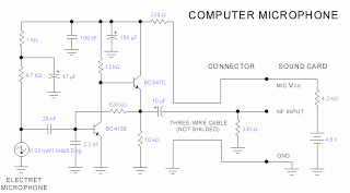
This microphone circuit was submitted by Lazar Pancic from Yugoslavia. The sound card for a PC typically features a microphone input, speaker output, and occasionally line inputs and outputs. The microphone input is designed specifically for dynamic microphones with...