
Electronic Circuit Schematic Dimmer LED using LM555 for Photo/Build Light

The LM555 timer is a highly adaptable integrated circuit that can operate in astable, monostable, and bistable modes. In this application, it is configured in monostable mode to create a delay timer for dimming LEDs. The timing interval is determined by the values of the resistor (P1) and capacitor (C1), where the time period (T) can be calculated using the formula T = 1.1 * R * C. The selection of a 50K potentiometer allows for variable resistance, enabling fine-tuning of the delay time.
The output from pin 3 of the LM555 provides a square wave signal that can effectively drive an NPN transistor. The transistor acts as a switch that can control larger loads, such as multiple LED strings, without being directly powered by the LM555. When the output from pin 3 goes high, it allows current to flow through the base of the NPN transistor, thereby turning it on and allowing current to pass through the collector-emitter path, illuminating the LEDs.
For applications requiring more power, the use of transistors like the D400 or TIP31 is recommended. These transistors can handle higher currents and voltages, making them suitable for driving multiple LED strings. The configuration allows for the control of more than nine LEDs in series, depending on the power supply and the specifications of the chosen transistor.
In summary, the LM555 timer IC serves as a reliable component for creating adjustable delay timers in LED applications. The integration of an NPN transistor enhances the circuit's capability to manage higher power loads, providing flexibility in various electronic designs.Maybe you ever use LM555 as timer project before, yes it also nice if you want to make analog timer using LM555. According datasheet LM555 this IC can use for several purpose in electronic project like to adjust timer according time needed.
From figure 1 above, we can describe that we can adjust dimmer LED with adjust P1 50K that connected with C1 to make delay time. Output of schematic above is pin number 3 as clock signal as input for NPN transistor. NPN transistor will work like switch that controlled from output signal from pin number 3 LM555. You can use all series of NPN transistor like D400, TIP31, etc according the power that you want to turn on and turn off the LED strings. With high power you can make more arrange LED strings more than 9 LED strings. Thank you very much for your visiting in Robometricschool blog, We hope you will get more information about Robotic, Mechatronic, and Electronic.
And don`t forget to give us your comment about this article. Let keep for building comment. 🔗 External reference
Related Circuits
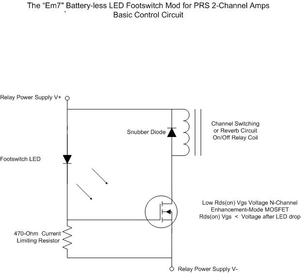
For individuals seeking LED-based footswitching without the inconvenience of battery installation, a battery-less LED-based footswitch modification is being developed for 2-channel amplifiers. This solution is designed to work with the existing TRS jack and footswitch, and it will involve...
The circuit is designed to provide a reminder for lights using a monostable delay configuration. It comprises a monostable delay circuit, a driving circuit, a buzzer, light-emitting diodes (LEDs), and other components. The output signal from the delay circuit,...
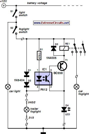
A rear fog lamp is mandatory for trailers and caravans to enhance visibility during foggy conditions. When the fog lamp is activated, the fog lamp of the towing vehicle must be turned off to prevent distracting reflections. To achieve...
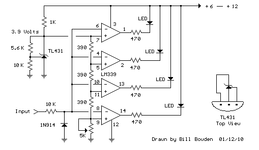
This circuit functions similarly to the previous one and features a 4 LED bar graph that displays the voltage of a common 3.6-volt lithium-ion rechargeable cell phone battery. The reference voltage is supplied by a TL431 programmable voltage source,...

The simplicity of a traditional die makes it exceptionally difficult to create a fully equivalent electronic version, primarily because an electronic version requires a power supply and a collection of electronic components that occupy a significantly larger volume than...
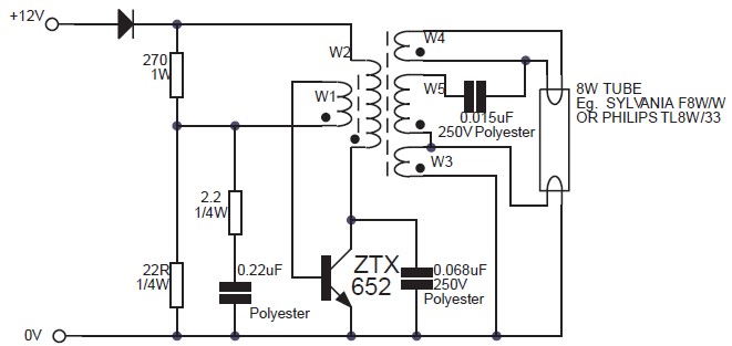
This circuit is an 8W inverter designed to drive an 8W fluorescent lamp from a 12V power supply, utilizing an inexpensive inverter based on a ZTX652 transistor. The inverter operates from power supplies ranging from 10V to 16.5V, achieving...