
Invert a 555 Astable Output Signal
To implement the described functionality, a 555 timer can be configured to serve as an inverter in conjunction with the existing astable configuration. The primary 555 timer produces a square wave output that controls the two MOSFETs. The secondary 555 timer, configured in monostable mode, can be triggered by the falling edge of the output from the first timer. This configuration allows for precise timing control, ensuring that the third MOSFET turns ON immediately as the first two turn OFF.
The setup involves connecting the output of the first 555 timer to the trigger input of the second 555 timer. A capacitor can be placed between the output of the first timer and the trigger pin of the second timer to ensure that the second timer is triggered by the falling edge of the signal, creating a sharp transition. The second timer can be adjusted to have a short pulse width, which will drive the third MOSFET ON for the duration that the first two are OFF.
For the MOSFETs, it is essential to select devices that can handle the required load and switching speeds. The gate drive circuit for the MOSFETs should be designed to provide sufficient drive current to ensure fast switching. This can be achieved by using gate resistors that are low enough to allow for quick charging and discharging of the gate capacitance, thereby minimizing rise and fall times.
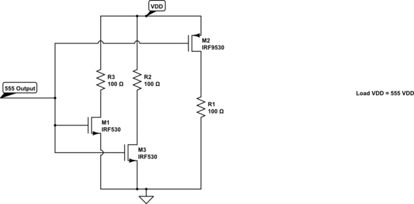
Overall, this approach maintains simplicity while achieving the desired control over the MOSFETs, ensuring that the output characteristics meet the specified requirements without introducing excessive complexity into the circuit design.A variable frequency, variably duty cycle 555 configuration in astable mode. I`m using a set of pots to get a wide range of control. It works beautifully. The output is great, but I have a problem. I am driving a couple mosfets directly from the output. But I want to have a third mosfet that turns on and off opposite to the timing of the first two. So if I`m running 25% duty cycle, the first two are ON for 25% of the cycle while the third one is OFF during that portion and then reverse this for the OFF period of the cycle. I`ve seen some diagrams that talk about using one extra mosfet or one extra transistor along with a resistor to invert a signal, but they don`t create hard/fast rise and fall times.
The resistor causes slow rise times. I want a nearly perfect inversion of the square signal. Right at the moment that the first two mosfets flip off, the third mosfet needs to flip full on. It`s critical that I get this to be as accurate as is feasible without getting into overly complex circuitry. Anything more than two or three 555s and/or two or three extra transistors (possibly needed to invert the signal) is more than I`m bargaining for.
I`m not posting this as an answer yet, because I`m waiting to hear a response from the other answerer. But apaprently you can run a 555 as a 200mA signal inverter. This is really simple for a person who already has 555s on hand, and the best part is that the 200mA current is WAY higher than a typical logic unit inverter (often topping out at least than 10 or 20mA).
Here`s a page with a circuit at the bottom explaining Inverter mode: 🔗 External reference
Related Circuits
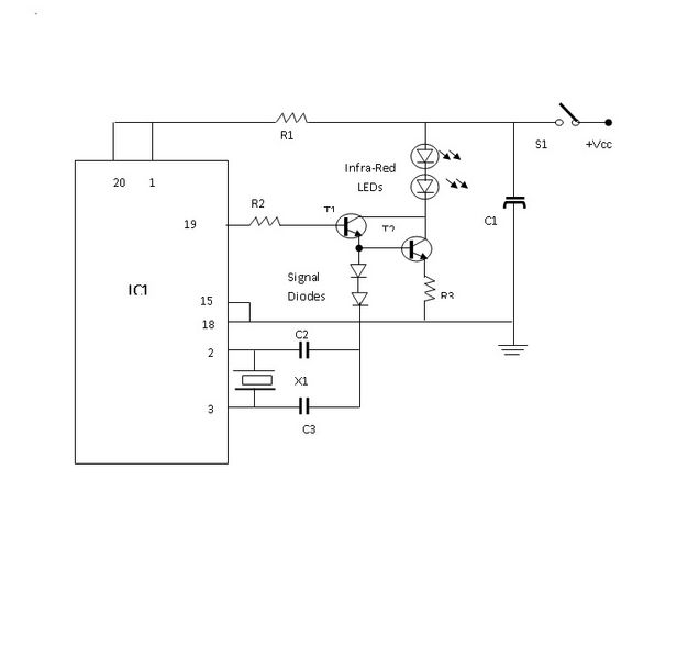
The objective of this project is to prevent vehicle collisions by utilizing an ultrasonic anti-collision device. This device is mounted on the front of the vehicle and detects nearby vehicles or obstacles. The ultrasonic anti-collision system operates by emitting ultrasonic...
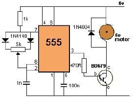
This project utilizes a 555 timer to control the speed of a 6-volt DC motor. Speed adjustment is achieved by rotating a 50 kΩ potentiometer either to the left or right. The circuit employs the 555 timer in astable mode,...
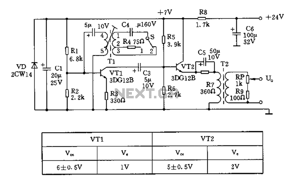
The 450/800Hz oscillation circuit depicted in the figure utilizes transformer coupling. The frequency conversion is achieved by varying the inductance through a variable filter tap (T1). When the switch control signal (S) is set to position 1, the oscillator...
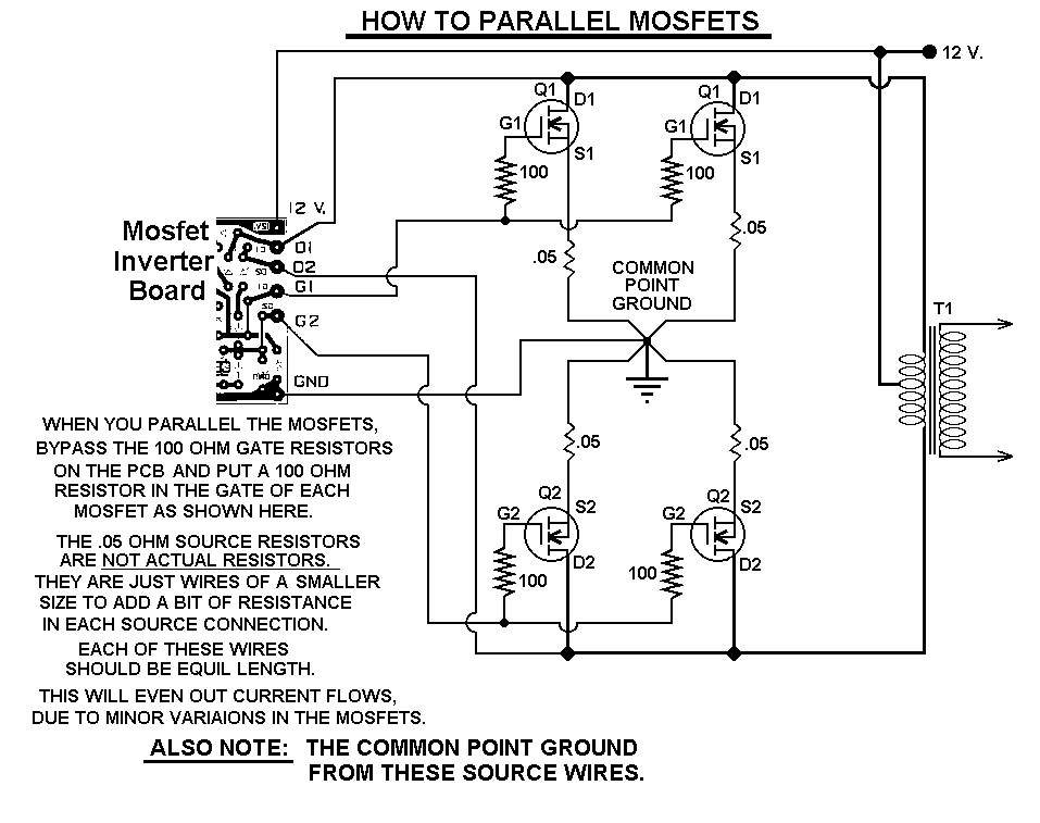
This 1000-watt power inverter circuit diagram utilizes the MOSFET RF50N06. To achieve higher power output, additional MOSFETs can be connected in parallel with the RF50N06. These MOSFETs are rated for 60 volts and 50 amps. It is essential to...
A 40-watt fluorescent tube lamp or two 20-watt tubes in series will be driven by this circuit. The transformer is wound on a ferrite rod with a diameter of 10 mm and a length of 8 cm. The circuit described...
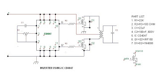
The post discusses how to modify an ordinary square wave inverter using IC 4047 into a modified sine wave inverter through PWM technology. The idea was requested by Mr. Philip, a resident of Nigeria, who has been an avid...