
Inverter as high voltage low current source
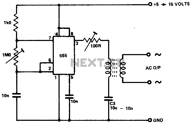
This circuit utilizes the 555 timer IC in astable multivibrator configuration to generate a square wave output, which is essential for driving a transformer. The frequency of oscillation can be adjusted by varying the values of the resistors and capacitor in the timing network. The output frequency must be optimized to match the resonant frequency of the transformer, ensuring efficient energy transfer and minimizing losses.
The output from the 555 timer is connected to a limiting resistor, which protects the circuit from excessive current that could damage the components. The primary coil of the transformer is connected in series with this resistor, allowing the magnetic field to build up when the output is high. The energy stored in the magnetic field is then transferred to the secondary coil of the transformer when the output switches low, leading to a reversal of current flow. This mechanism is critical for maintaining a continuous and efficient power supply to the connected devices.
Capacitor C3 plays a vital role in smoothing the output voltage and providing stability to the circuit. By selecting an appropriate capacitance value, the output can be made more symmetric, which is crucial for applications requiring precise voltage levels. The circuit's design allows for flexibility in component selection, enabling it to cater to various load requirements while ensuring reliable operation across different scenarios. Overall, this power supply circuit is well-suited for portable applications that demand efficiency and stability.The circuit is capable of providing power for portable Geiger counters, dosimeter chargers, high resistance meters, etc. The 555 timer IC is used in its multivibrator mode, the frequency adjusted to optimize the transformer characteristics.
When the output of the IC is high, current flows through the limiting resistor, the primary coil to charge C3. When the output is low, the current is reversed With a suitable choice of frequency and C3, a good symmetric output is sustained. 🔗 External reference
Related Circuits
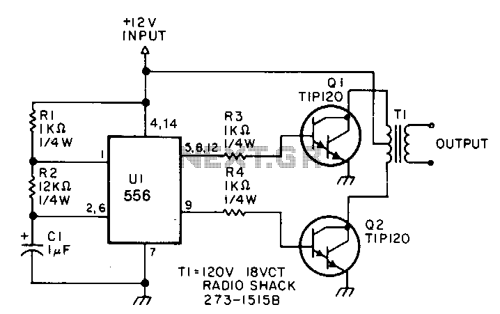
This low-power inverter utilizes only nine components to convert 10 to 16 VDC into a 60 Hz, 115 V square-wave output suitable for operating AC equipment with a maximum power of 25 W. The initial section of the 556...
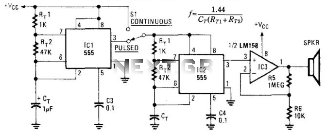
This circuit utilizes two NE555 timer IC devices to generate either pulsed or continuous ultrasonic signals. The values of CT for both pulse rate and ultrasonic frequencies can be calculated accordingly. SPKR refers to a small hi-fi tweeter. The circuit...
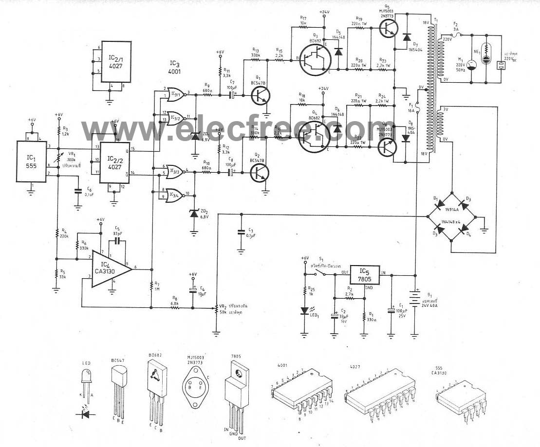
This circuit is a 300W inverter power converter, which takes a 24V input battery and outputs 220V AC at 50Hz with a maximum power of 300W. The main components used in this circuit include the IC CD4027, NE555, CA3130,...
This power supply was designed for ham-radio use and has been in operation for over 10 years. Its design is very simple and practically immune to RF. It is assembled from discrete components, being the most costly element a...
RS-232C serial port lines are quite prone to be damaged by overvoltages. The damage to computer serial ports has become more and more expensive to replace because of higher integration: usually, you have to buy a new motherboard if...
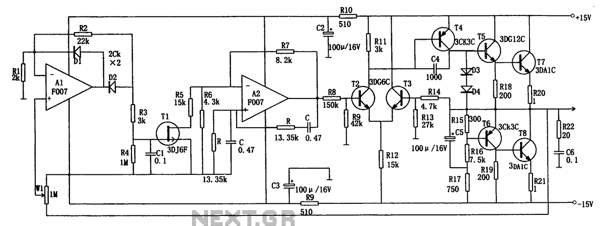
The low-frequency signal generating circuit demonstrates excellent performance characterized by stable operation, high output power, and minimal waveform distortion. It serves as an ideal source for low-frequency measurement signals. The circuit includes an operational amplifier (A) with a feedback...