
300W inverter power 24Vdc to 220Vac by MJ15003CA3130CD4027
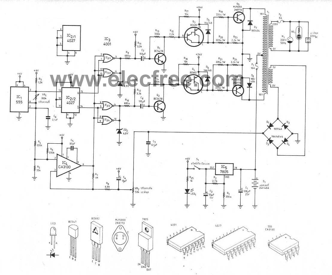
The 300W inverter circuit converts a 24V DC input from a battery into a 220V AC output suitable for powering various household appliances. The core of the inverter relies on the CD4027 dual JK flip-flop, which is used to generate the necessary square wave signal that drives the power transistors. This square wave is essential for creating the alternating current (AC) output.
The NE555 timer is configured in astable mode to provide a timing pulse that controls the frequency of the output waveform. By adjusting the resistors and capacitors connected to the NE555, the frequency can be tuned to achieve the desired output of 50Hz.
The CA3130 operational amplifier is utilized for signal conditioning and amplification. It enhances the performance of the circuit by providing a stable reference voltage and ensuring that the output waveform remains consistent and free from distortion.
To regulate the voltage supply for the control circuitry, the LM7805 voltage regulator is employed. It steps down the voltage to a stable 5V, which is required by the logic components of the inverter.
The power stage of the inverter typically consists of transistors or MOSFETs that switch the DC input on and off rapidly, creating the necessary AC waveform at the output. Adequate heat sinking and protection mechanisms should be implemented to ensure reliable operation under load conditions.
Overall, this inverter design is capable of efficiently converting low-voltage DC power into standard household AC power, making it suitable for various applications, including backup power systems and portable power supplies. Proper consideration of component ratings and thermal management will enhance the longevity and performance of the inverter circuit.This is circuit 300W Inverter power,so input battery 24V to Output 220Vac 50Hz 300W. I used main Component IC CD4027 , NE555,CA3130 and LM7805. The transistor.. 🔗 External reference
Related Circuits
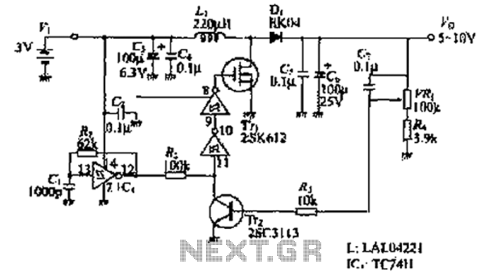
The design of the power supply circuit diagram utilizes an oscillator circuit from the 74HC series of CMOS logic circuits, with a MOSFET as the switching device. This configuration allows for the development of small-scale power supplies suitable for...

The circuit of the transmitter is depicted in Figure 1, showcasing its simplicity. The initial stage is the oscillator, which is tuned using a variable capacitor. To select an unused frequency, adjust C3 carefully until background noise ceases (the...
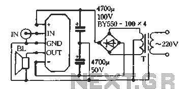
The D amplifier utilizes a series fool manifold and can easily be configured as a mono output transformerless (OTL) or output capacitorless (OCL) audio power amplifier. Figure 3-12 illustrates a single-channel power output typical application wiring diagram for OTL....
This is an astable multivibrator (oscillator) circuit utilizing a CMOS inverter. The circuit employs the CD4007 or MC14007 components. It operates within a frequency range of... The astable multivibrator circuit is designed to generate a continuous square wave output without...
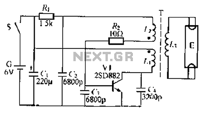
The circuit described is a battery-powered fluorescent lamp system designed for temporary emergency lighting during power outages. It utilizes a transistor (V7) and a boosting transformer (T) along with an inductive feedback oscillator to generate a high-voltage output. When...
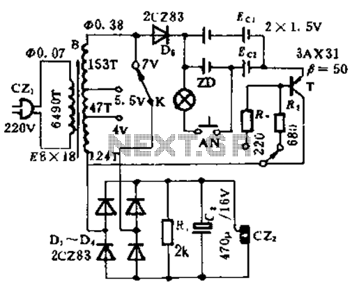
This circuit is designed for high current applications using nickel-cadmium rechargeable batteries, and it can also function as a general low-voltage DC power supply. The circuit consists of a charging section and a DC output section. K2 serves as...