
13.8V/40A Stabilized high Power Supply

The power supply circuit is designed to deliver a stable output voltage suitable for ham-radio applications, characterized by its robustness and reliability over an extended operational period. The core of the power supply is the 600VA toroidal transformer, which is essential for stepping down the mains voltage to a usable level while providing sufficient current capacity. The transformer should be selected with a primary voltage compatible with the local mains supply and a secondary voltage in the range of 17V to 20V, ensuring that it meets the power requirements of the application.
The regulation of the output voltage is achieved through a feedback mechanism involving a 7.5V Zener diode (D3) that establishes a reference voltage. This reference is compared to the output voltage via a resistive divider composed of resistors R5, R6, and the variable resistor VR2, which allows for fine-tuning of the output voltage. The operational amplifier Q2 compares these voltages and adjusts the base current of the Darlington pair Q3, which in turn drives the output stage.
The output stage consists of a driver transistor Q4 and four power transistors (2N3771), configured in a parallel arrangement to handle the high current demands of the load. The collector of these transistors is grounded, allowing for direct mounting on a heatsink without electrical isolation. Adequate heatsinking is critical to prevent thermal failure, and the use of a large heatsink that may also serve as part of the chassis is recommended. Additionally, forced air cooling through a thermostat-controlled fan can enhance thermal management, ensuring that the transistors operate within safe temperature limits.
The current limiting feature is implemented using transistor Q1, which is adjustable via the potentiometer VR1. This feature prevents excessive current draw that could potentially damage the circuit or connected loads. The overload indicator LED (DL2) provides a visual indication of an overload condition, alerting the user to take corrective action.
Protection against short circuits is an essential aspect of the design. The power supply is engineered to enter a low-power state during a short circuit, effectively preventing damage and allowing for indefinite operation in this state without risk. It is important to note that certain conditions, such as using cables with appropriate ratings, may lead to situations where high current is supplied without triggering the short circuit protection.
The rectification of the AC voltage from the transformer is accomplished using power rectifier diodes (D1, D2), which should be of the threaded metallic type with their cathodes grounded. These diodes must be adequately heat-sinked to handle the power dissipation during operation. The careful selection and mounting of these components contribute significantly to the overall reliability and performance of the power supply.This power supply was designed for ham-radio use and has been in operation for over 10 years. Its design is very simple and practically immune to RF. It is assembled from discrete components, being the most costly element a 600VA toroidal transformer, which can be replaced by another with different characteristics, provided it has a voltage of between 17~20V and the right power for our needs. The reference voltage is obtained from a 7.5V Zenner diode (6V8 ~ 8V2) applied to Q2 which compares the voltage output by the resistive divider formed by R5, VR2 and R6, controlling the Darlington amplifier Q3 which is responsible for driving the output stage consisting of driver Q4 and 4 NPN power transistors 2N3771, which can be mounted directly to the heatsink without being isolated, because its collector is connected to ground.
The source has maximum current limiter (Q1) adjustable via VR1 and overload indicator LED (DL2) and total protection against short circuit, with zero consumption in case of short circuit, can be maintained in this state indefinitely without danger. (Keep in mind that due to the high power of the PSU a occasional short with a high length or small section cable that has sufficient strength not to exceed the maximum current of 40A.
Might not be considered a short circuit and cause the PSU supplying a high amount of power). The power rectifier diodes (D1, D2) are recommended metallic threaded type with the cathode grounded, mounted on a large enough heatsink isolated from the chassis. For the power transistors using a heatsink as big as possible, without being isolated as discussed above, may be part of the aluminum chassis of the box.
We also recommend the use forced ventilation with a thermostat. 🔗 External reference
Related Circuits
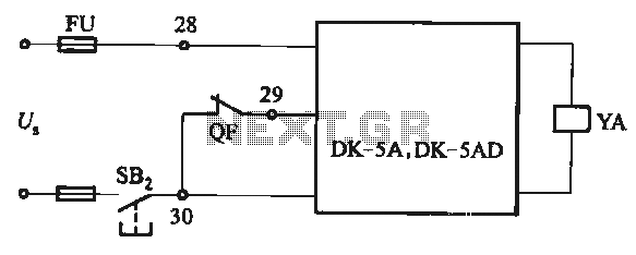
The DK-5A and DK-5AD AC power control circuit is illustrated in Figure 6-77. The figure includes a closing button (SBz) and a line (YA) connected to the closing electromagnet coil (U). This circuit is designed for the operation of...
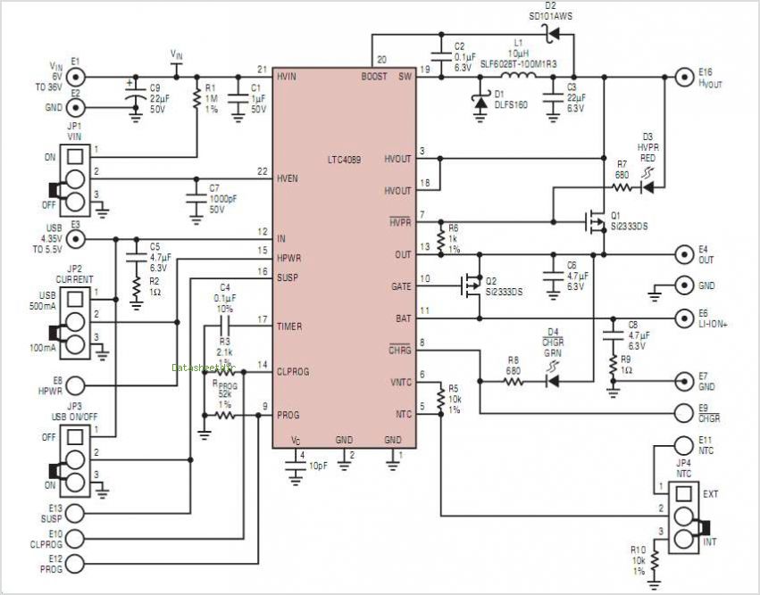
MSP430 microcontroller and I2C-compatible slave peripheral device. Temperature measurement tasks can be accomplished in a variety of ways. The MSP430 microcontroller is a low-power, 16-bit device widely used in embedded systems, particularly for applications requiring efficient power management and precise...
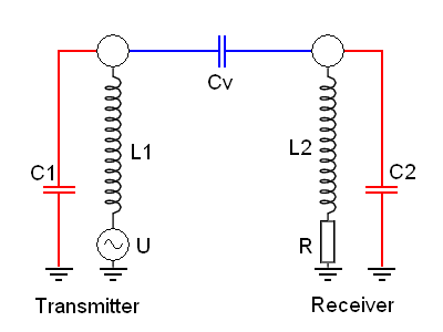
This project is a successor to SSTC1, which has been retired. The purpose of this coil is to operate with its breakout suppressed, demonstrating the concept of wireless power that Tesla himself worked on during his time. Further videos...
The MOSFET input of the CA3140 is ideally suited for use in a high impedance DC voltmeter. The range selector is controlled by switch S1. The input impedance is limited to 10M by the resistors in the voltage divider,...
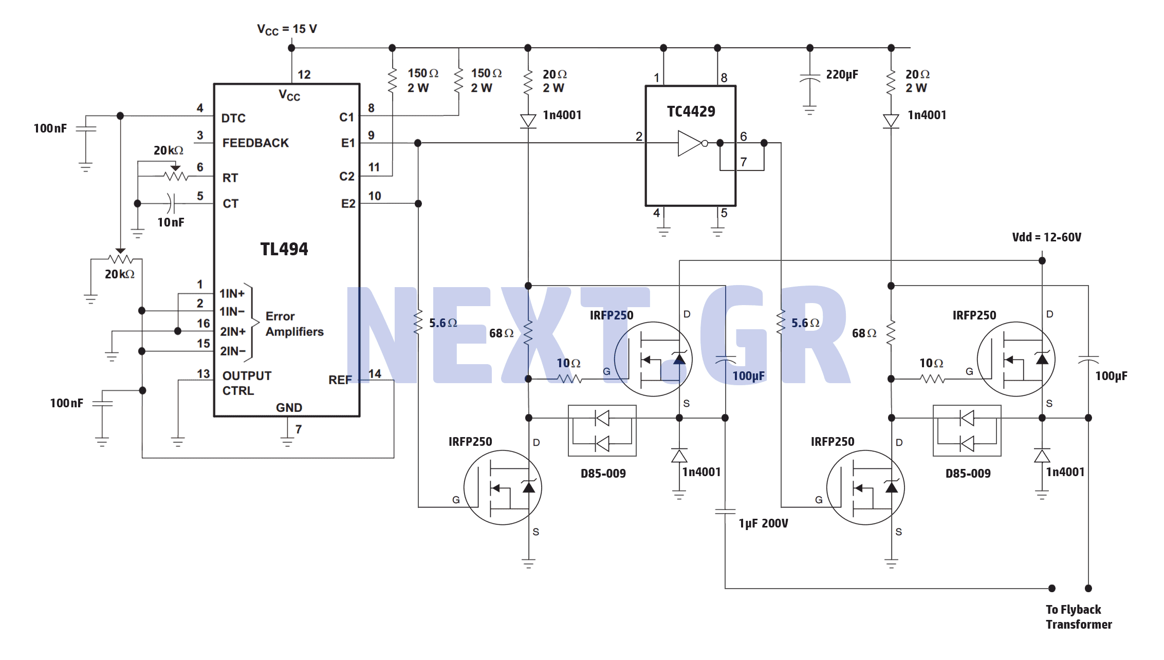
A reliable full bridge driver is essential for driving a flyback transformer. While many flyback driver schematics exist, most lack durability. The well-known Zero Voltage Switching (ZVS) driver, invented by Vladmiro Mazilli, is recognized for its reliability due to...
The goals were achieved by utilizing a discrete-component operational amplifier (op-amp) driving a bipolar junction transistor (BJT) complementary common-emitter output stage configured for Class B operation. In this configuration, the output transistors remain off for small output currents, allowing...