Inverter/Charger relay
After experiencing equipment failure, a decision was made to replace a combination inverter/charger unit with individual components that fulfill the same requirements. The combination unit, referred to as the "Everything Box," is an efficient solution for cost savings by integrating various electronic functions and sharing hardware. However, if it fails, all functions are lost simultaneously. The failure of the unit prompted the desire to avoid a similar situation in the future. A block diagram illustrating the proposed solution is provided. Most of the system can be assembled using off-the-shelf components, with the exception of the line/inverter relay box, which must be constructed from scratch. The line/inverter relay box is designed to switch 30 amps, potentially over-engineered for typical small boat applications. The primary function of this circuit is to switch from shore power to inverter power when the house-power inverter is activated. This box connects to the boat's breaker panel, ensuring that only loads requiring inverter power, such as specific outlets for computers and video equipment, are connected. High-power devices, like microwaves, should not be powered unless a sufficiently large inverter and battery bank are utilized. Additionally, the battery charger must always remain connected to shore power. It is crucial not to simplify the circuit by omitting neutral wiring, as modern house wiring mandates that neutral lines be switched alongside hot lines to ensure proper operation of GFI outlets. The barrier strip originally used with #6 hardware was deemed inadequate; a larger size, such as #8 hardware, would have been more suitable. A warning is issued against placing this box in a gasoline-powered boat's engine compartment unless it is completely sealed to prevent explosion risks during relay switching. Initially, the intention was to order a standard 120V 30A DPDT relay online, but complications arose due to discrepancies between the relays received and their descriptions, leading to multiple returns.
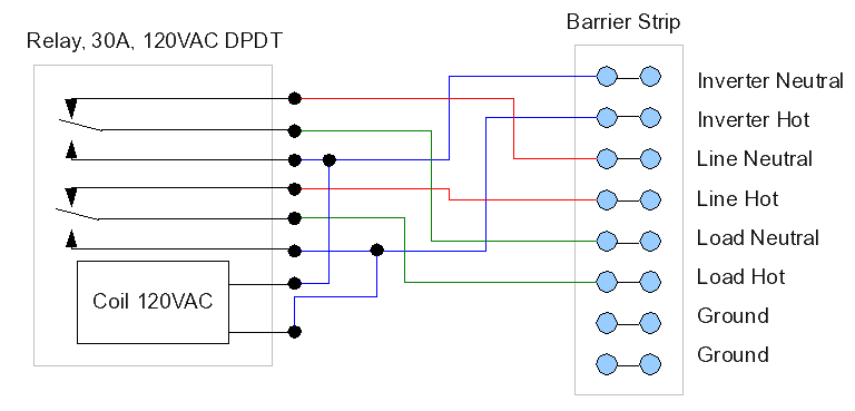
The proposed electronic schematic for the line/inverter relay box incorporates a double-pole, double-throw (DPDT) relay capable of handling 30 amps. The relay is activated by the house-power inverter, which switches the circuit from shore power to inverter power. The schematic includes connections for the input from shore power and the output to the inverter, ensuring that only designated loads are powered by the inverter.
The relay contacts are rated for the necessary amperage and voltage, ensuring reliable operation under typical load conditions. The design features a barrier strip for secure connections, although it is recommended to use #8 hardware for improved compatibility with terminal sizes. The circuit also includes a dedicated neutral wiring path, which is essential for compliance with modern electrical standards, particularly in relation to GFI outlet functionality.
The box should be constructed with materials that are resistant to environmental factors, especially if installed in a marine setting. Adequate sealing must be ensured to protect against moisture and potential ignition sources, particularly in gasoline-powered vessels.
Overall, this schematic provides a robust solution for transitioning power sources on a small boat while addressing safety considerations and ensuring compliance with electrical codes.As explained elsewhere in this article set, after an equipment failure I decided to replace a combination inverter/charger unit with individual components that fill the same needs. The combination unit (the "Everything Box") is an efficient way to save costs by combining certain electronic functions and sharing hardware, but if it should fail, all
its functions are lost at once. Mine failed, and I decided I would like to avoid repeating that experience. Here is a block diagram of my solution: Most of this system can be put together from off-the-shelf components, in fact, everything except the line/inverter relay box, which it seems must be built from scratch. Here is a diagram of my line/inverter relay box, able to switch 30 amps and perhaps a bit overdesigned for the average small boat: The basic idea of this circuit is that activating the house-power inverter causes the relay to switch from shore power to inverter power.
This box is wired into the boat`s breaker panel in such a way that only those loads that need inverter power are connected to it ” for example, a select number of outlets serving computers and video equipment, but not high-power equipment like microwaves (unless you buy a very large inverter and have a huge battery bank) and certainly not loads like the battery charger, which should always be connected to shore power. Don`t consider simplifying this circuit by eliminating the neutral wiring ” in modern house wiring, the neutral lines must always be switched along with the hot lines, among other reasons to allow GFI outlets to function as they should.
In fact, the barrier strip with #6 hardware was a mistake, and if I were to do this over again, I would get a bigger size ” like #8 hardware ” because the existing terminals didn`t easily fit on this small strip. Warning: if someone decides to put this box on a gasoline-powered boat, either don`t put it in the engine compartment, or make sure the box is totally sealed up to avoid the possibility of an explosion when the relay switches.
When I started this project, I thought I would just order the first 120V 30A DPDT relay that I could find on the Internet. After all, this is a common, generic item, how could I go wrong But I was once again reminded how tricky online shopping can be, and I ended up returning a lot of relays when they turned out not to resemble their descriptions.
Here are some details. 🔗 External reference
