
Inverter Circuit

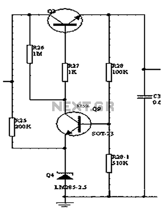
The described inverter circuit employs a simple yet effective design that maximizes efficiency while minimizing component count. The core of the circuit consists of two transistors configured in a push-pull arrangement, allowing for alternating current (AC) generation from a direct current (DC) source. The power supply for the circuit can be sourced from a standard vehicle battery, providing a practical solution for outdoor applications.
The transformer plays a crucial role in this design, as it steps up the voltage to the desired level for the output. The choice of transformer is essential, as it must be capable of handling the expected power levels and frequency. The winding configuration should be designed to ensure that the two halves of the circuit are balanced, even though slight imbalances may exist.
The feedback mechanism inherent in this design allows for self-regulation of the output voltage and current. When one transistor begins to conduct, it initiates a feedback loop that helps stabilize the operation and maintain consistent output. This regenerative behavior is particularly advantageous, as it enhances the overall efficiency of the inverter.
In terms of component selection, resistors should be chosen with precision to ensure that the biasing conditions for the transistors are optimal. The use of high-quality capacitors can further enhance performance by smoothing out voltage fluctuations and improving transient response.
Overall, this mini inverter circuit represents an efficient and cost-effective solution for powering small electronic devices, combining simplicity in construction with reliable performance. The design is well-suited for hobbyists and those seeking an affordable means of generating AC power from a DC source.This super simple design of aninvertercircuit does not limit it in any way from providing a high output power and an efficiency of a good 75%. Learn how to build aninverterthat will satisfy most of your power requirement at quite an affordable cost.
The article deals with the construction details of a miniinverter. Read to know how to build aninve rterwhich can provide reasonably good power output and yet is very affordable and sleek. There may be a huge number ofinvertercircuits available over the internet and electronic magazines. But these circuits are often very complicated and hi-end type of inverters. Thus we are left with no choice but just to wonder how to build aninverterthat can be not only easy to build but also low cost and highly efficient in its working. Well your search for such a circuit ends here. The circuit of aninverterdescribed here is perhaps the smallest as far its component count goes yet is powerful enough to fulfill most of your requirements.
I hope from the above discussions you must have clearly understood how to build aninverterwhich is not only simple to construct but also very affordable to each of you. It can be used to power small electrical appliances like soldering iron, CFL lights, small portable fans etc.
The output power will lie in the vicinity of 70 watts and is loaddependent. The efficiency of thisinverteris around 75%. The unit may be connected to your vehicles battery itself when outdoors so that the trouble of carrying an extra battery is eliminated. The functioning of this miniinvertercircuit is rather unique and different from the normal inverters which involve discrete oscillator stage for powering the transistors.
However here the two sections or the twoarms ofthe circuit operate in a regenerative manner. Its very simple and may be understood through the following points: The two halves of the circuit no matter how much they are matched will always consist a slight imbalance in the parameters surrounding them, like the resistors, Hfe, transformer winding turns etc. Assume that the upper half transistors conduct first, obviously they will be getting their biasing voltage through the lower half winding of the transformer via R2.
🔗 External reference
Related Circuits
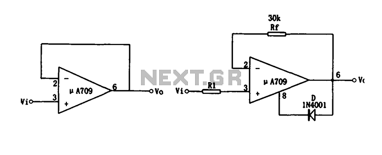
Figure (a) illustrates a voltage follower circuit, which serves as a specific instance of an in-phase amplifying circuit. The input signal originates from an integrated operational amplifier. At the conclusion of the introduction phase, the feedback resistor is set...
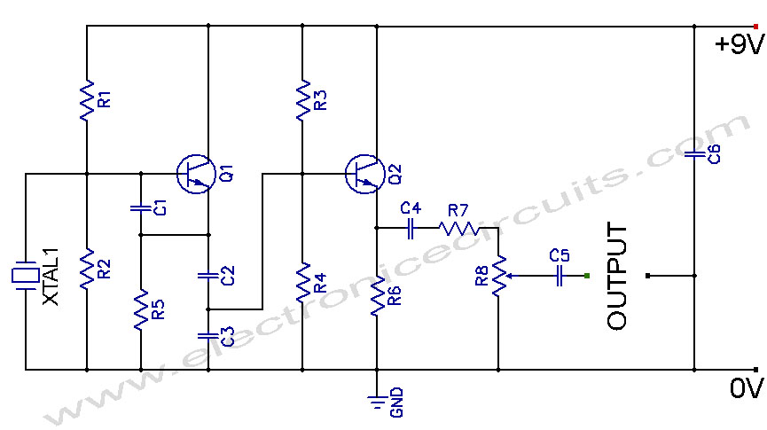
Crystal Controlled Oscillator Circuit. This general-purpose signal source is highly effective in signal-tracing applications. The output level is adjustable. The crystal-controlled oscillator circuit is designed to provide a stable and precise frequency output, which is essential for various electronic applications,...
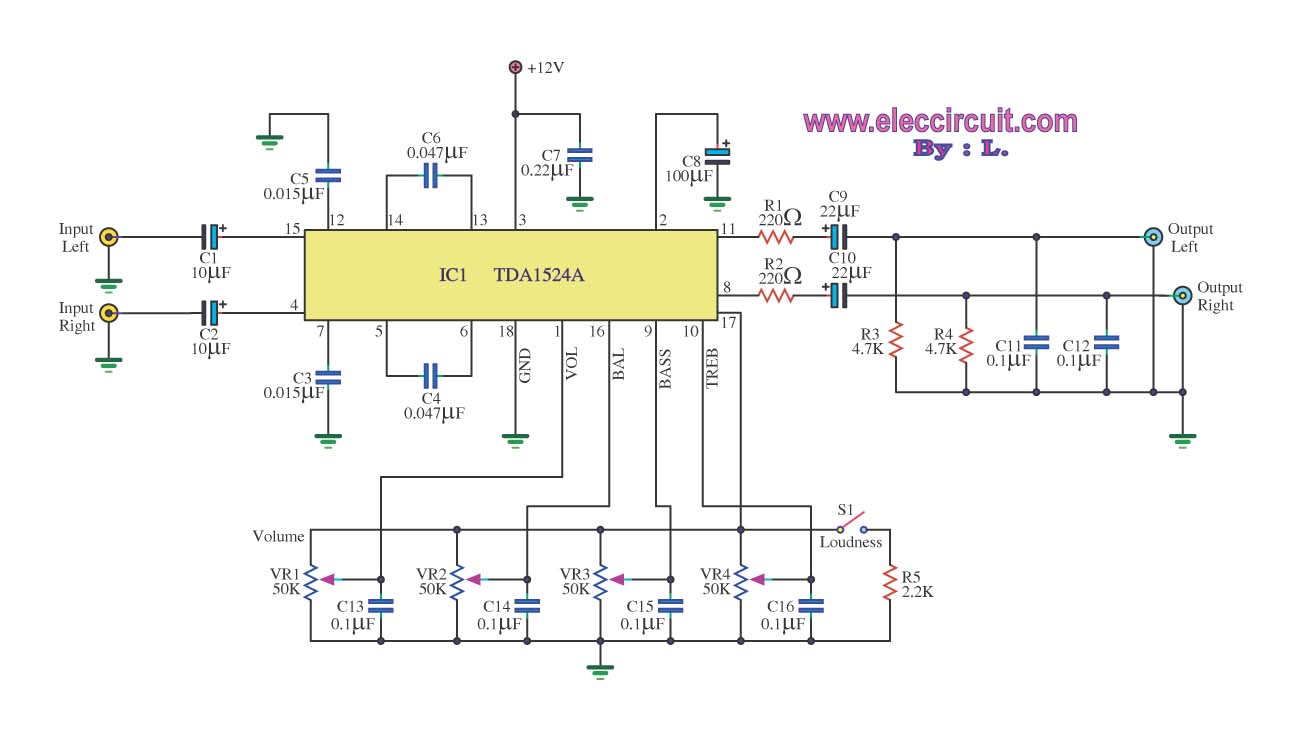
The stereo tone control circuit utilizes the integrated circuit TDA1524A. This IC serves as the central component in the design. The TDA1524A is a versatile integrated circuit designed for audio applications, particularly in tone control systems. It features a dual-channel...
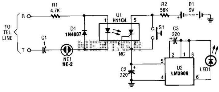
The circuit is constructed using a pair of low-cost integrated circuits (ICs): an H11C4 optoisolator/coupler with a silicon-controlled rectifier (SCR) output (U1) and an LM3909 LED flasher (U2). It connects to the phone line in the same way as...
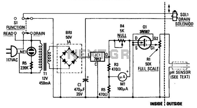
The drain-to-source resistance of Q1 varies depending on the acidity of the sample presented to Q1's gate circuit. This variable resistance influences the current flowing through the bridge, which is proportional to pH. The circuit involves a field-effect transistor (FET),...
The program utilizes the Linear LT1934 chip for the production of a high-efficiency power supply circuit design that is less demanding in terms of electrical load. It offers considerable adjustment margins. When supplied with a 24VDC input, the non-isolated...
Warning: include(partials/cookie-banner.php): Failed to open stream: Permission denied in /var/www/html/nextgr/view-circuit.php on line 713
Warning: include(): Failed opening 'partials/cookie-banner.php' for inclusion (include_path='.:/usr/share/php') in /var/www/html/nextgr/view-circuit.php on line 713