
Telephone Voice Mail Alert Circuit
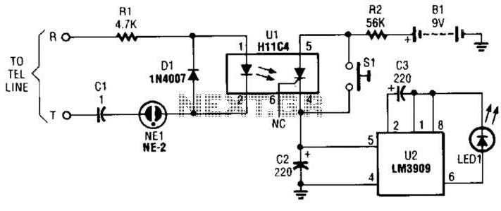
The described circuit serves as a notification system for incoming telephone calls by utilizing an H11C4 optoisolator and an LM3909 LED flasher. The H11C4 operates by isolating the phone line from the rest of the circuit, ensuring that any voltage spikes or noise from the line do not affect the downstream components. When a ring signal is detected on the phone line, the optoisolator activates its SCR output, which in turn triggers the LM3909.
The LM3909 is designed to control LED flashing patterns. Once activated by the SCR, it initiates a flashing sequence for LED1, providing a visual indication that a call is incoming. The flasher can be configured for different flashing rates and durations, allowing customization based on user preference.
The circuit's connection to the phone line mimics that of a standard extension phone, ensuring compatibility with typical telephone systems. The design is efficient, utilizing low-cost components that are readily available, making it an attractive option for hobbyists and professionals alike. This simple yet effective circuit can be employed in various applications where visual indication of incoming calls is desired, enhancing user awareness without requiring audible notifications. The cireiilt is built around a couple of low-cost ICs: an H11C4 optoisolator/coupler with an SCR output (Ul) and an LM3909 LED flasher (U2). It is connected to the phone line in the same manner as any extension phone. A ring signal on the telephone activates the opt,oisolator/SCR. and causes U2 to flash LED1. This flash signifies that a ring signal has been received. 🔗 External reference
Related Circuits
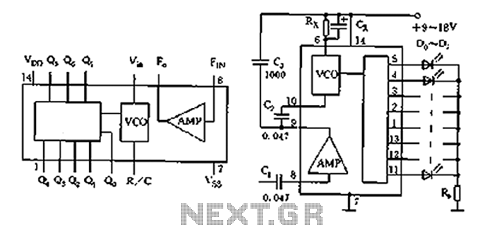
The circuit shown is a lighting control circuit that adjusts the speed of the flash output based on the strength of an audio signal. It utilizes eight flash integrated circuits (ICs) of the type LP188, which is housed in...
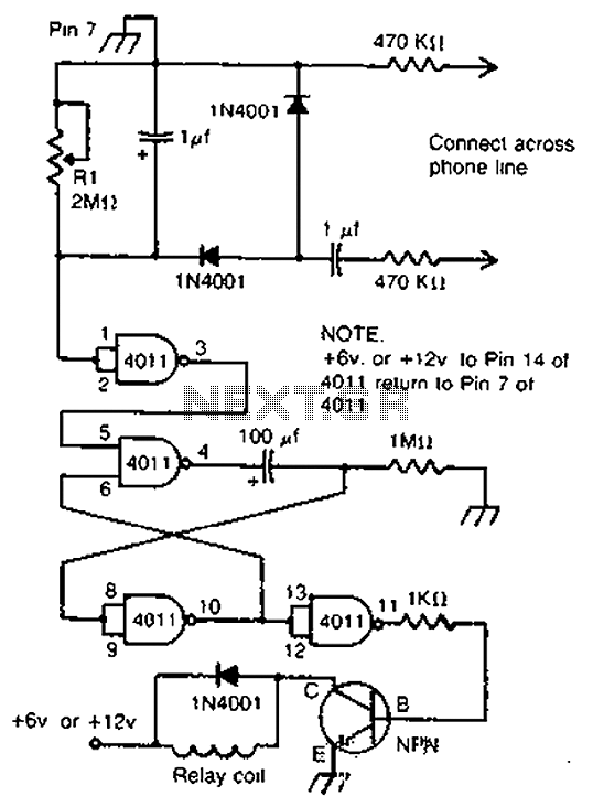
By cross-connecting the telephone ringing circuit, when the phone rings, the circuit activates the relay. It utilizes a delay in contact to drive various devices such as bells, sirens, buzzers, or lights. The telephone ringing circuit is designed to detect...
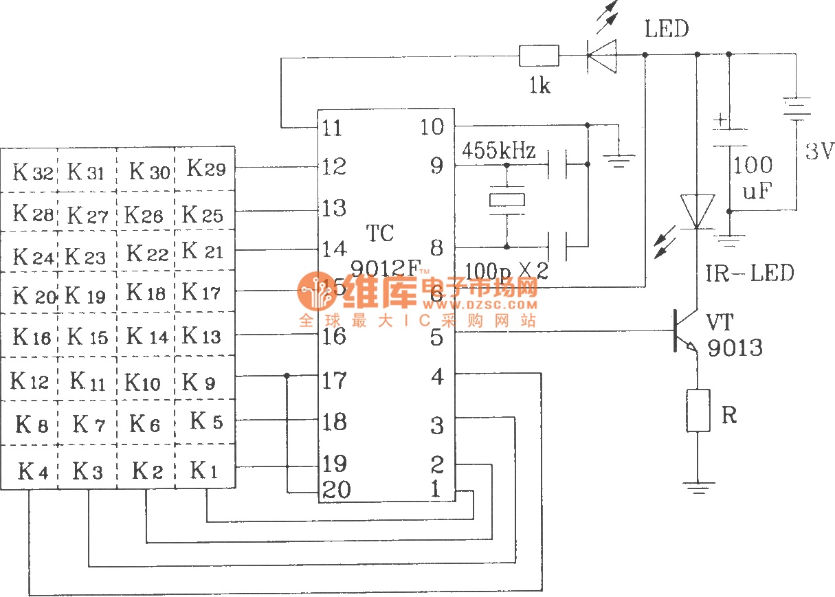
The TC9012 is a specialized off-screen remote control code transmitter. It incorporates an oscillator, divider timing generator, system code latch, data storage, key scan input, key scan output, and carrier control and output units. The internal 8-bit system code...
Electronics tutorial on mesh current analysis and examples of mesh analysis used to analyze complex electrical circuits in DC theory. Mesh current analysis is a powerful technique used in circuit analysis to determine the currents flowing in the loops of...
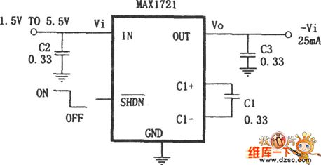
The MAX732/733 is a DC-DC current PWM step-up regulator. The MAX732 has an output voltage of +12V with a maximum output current of 200mA and an output voltage range of +4.0V to +9.3V. The MAX733 features an output voltage...
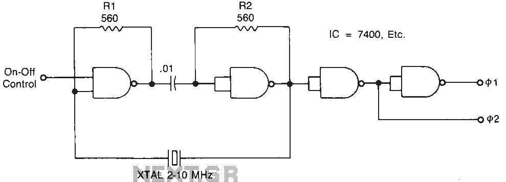
Temperature-stable resistors R1 and R2 are used in NAND gate configurations, ensuring that the switches operate in the linear region. Capacitor C1 functions as a DC component at the operating frequencies. Additionally, the impedance must remain below 0.1 ohm....