
power supply alarm circuit
The described circuit is a power supply failure indicator that operates without requiring an additional power source, making it efficient and practical for various applications. The core components of the circuit include an electrolytic capacitor, a transistor, a resistor, a potentiometer, and a buzzer.
The electrolytic capacitor serves as the energy storage element, allowing the circuit to maintain operation for a limited time after the main power supply has failed. This stored charge is essential for powering the alarm circuit, ensuring that it can sound an alert even in the absence of the primary power supply.
The circuit is designed to function with input voltages ranging from 5V to 15V, making it versatile for different power supply configurations. Calibration is achieved through the potentiometer (VR1), which adjusts the sensitivity of the circuit. By varying this potentiometer, the user can set the threshold at which the alarm will activate, ensuring that the buzzer operates within the desired parameters.
In the event of a power supply failure, the resistor (R2) plays a crucial role by pulling the base of the transistor low. This action saturates the transistor, allowing current to flow through the buzzer and activate the alarm. The result is an audible alert that indicates a loss of power, providing timely notification for maintenance or corrective actions.
This circuit design is particularly useful in environments where power reliability is critical and can be implemented in various electronic devices and systems that require monitoring of power supply status. The simplicity of the design, combined with the effectiveness of the alarm system, makes it a valuable component in power management solutions.Most of the power supply failure indicator circuits need a separate power supply for themselves. But the alarm circuit presented here needs no additional supply source. It employs an electrolytic capacitor to store adequate charge, to feed power to the alarm circuit which sounds an alarm for a reasonable duration when the supply fails. This circuit can be used as an alarm for power supplies in the range of 5V to 15V. To calibrate the circuit, first connect the power supply (5 to 15V) then vary the potentiometer VR1 until the buzzer goes from on to off. Whenever the supply fails, resistor R2 pulls the base of transistor low and saturates it, turning the buzzer ON.
🔗 External reference
Related Circuits
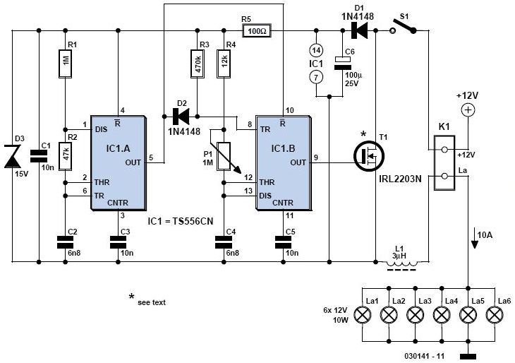
A light dimmer is quite uncommon in a caravan or on a boat. This document outlines how to create one, allowing for mood adjustment when needed. A light dimmer circuit is an essential component for enhancing the ambiance in confined...
This small transmitter can reach distances of more than 1 km under favorable transmission conditions. Modulation can be achieved using a microphone, such as an electret microphone, or another audio source. The transmitter includes a coil made of 5...
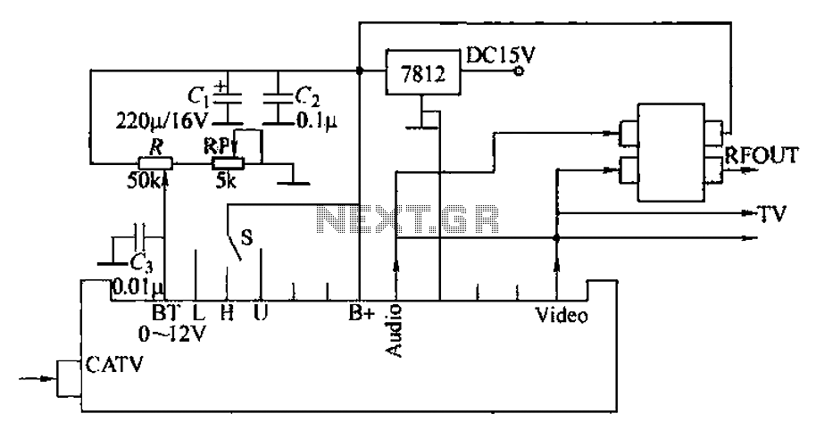
The circuit utilizes two main components: an integrated electronic tuner with AV output, commonly referred to as the tuner, which can receive CATV full channel TV signals and output a video signal (Vttko) along with an audio signal (Audio)....
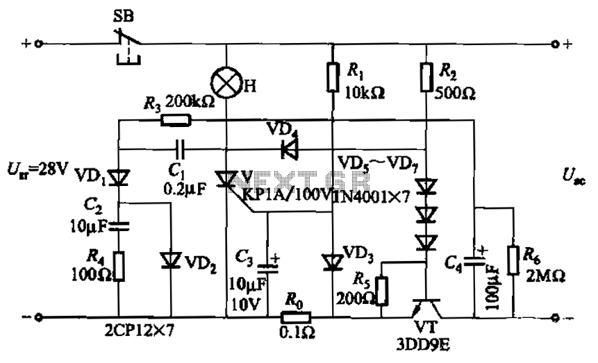
Capacitor C3 is used to determine the cutoff power, specifically the voltage threshold (VT cutoff), which influences the delay time selection. The schematic includes a reset button, SB, that is utilized to reset the system after a failure has...
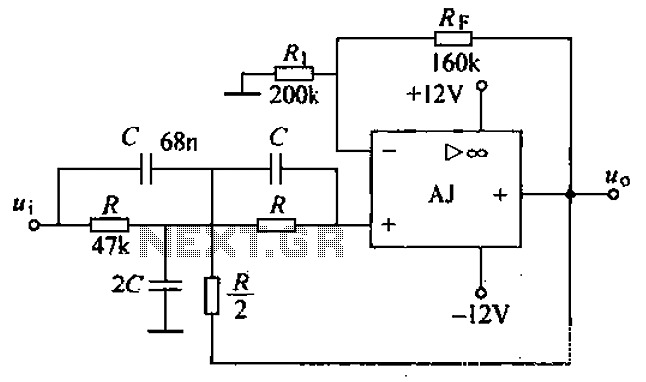
A band-stop filter (BSF) utilizing an integrated operational amplifier is designed to suppress signals within a specific frequency band, allowing signals outside this band to pass with minimal attenuation. This configuration is achieved through a two-stage network, which employs...
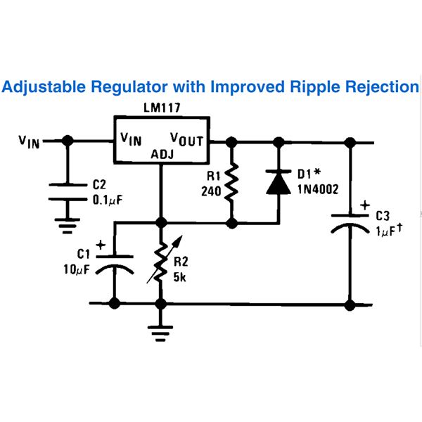
This document outlines the process of constructing an adjustable power supply utilizing the LM317 integrated circuit (IC). The LM317 is highly versatile, allowing for the creation of a wide variety of compact, high-quality power supply circuits. Various configurations can...
Warning: include(partials/cookie-banner.php): Failed to open stream: Permission denied in /var/www/html/nextgr/view-circuit.php on line 713
Warning: include(): Failed opening 'partials/cookie-banner.php' for inclusion (include_path='.:/usr/share/php') in /var/www/html/nextgr/view-circuit.php on line 713