
Single nozzle tracker circuit diagram
The circuit is designed to facilitate audio signal calibration and modulation detection. In inject mode, the calibration circuit produces a square wave output within the audio frequency range, allowing for the analysis and detection of harmonic distortions. These harmonics, which manifest as variations in frequency, can be observed at low frequencies, typically in the range of several Hertz. This feature is crucial for evaluating the performance of audio systems and ensuring they operate within specified parameters.
In tracking mode, the circuit transitions to detect non-linear operations of the amplifier. This is achieved by applying a 0.01 µF capacitor as a filter for the modulated RF signal. The capacitor serves to isolate the desired frequency components while attenuating unwanted high-frequency noise, thus enhancing the clarity of the received signal. The filtered signal is then routed to a headset, allowing for real-time monitoring of the audio output. This mode is particularly useful for applications requiring the detection of signal variations and quality assessment in communication systems.
Overall, the circuit's dual functionality in inject and tracking modes enables comprehensive testing and evaluation of audio and RF signal integrity, making it a valuable tool in electronic engineering applications. Circuit Description: Under inject mode, the calibration circuit provided in the audio range square wave output, power harmonics can be heard several Hertz. Under Tracking mode, the amplifier non-linear operation detecting modulated RF signal by 0.01 F capacitor filter and then input to the headset.
Related Circuits
A Butterworth filter is a type of filter characterized by a frequency response that is flat within the passband region. This filter was first described by British engineer Stephen Butterworth. A Butterworth filter is designed to provide a maximally flat...
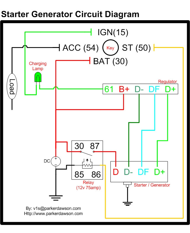
Circuit diagrams for both a Bosch and a Delco-Remy Starter-Generator are available, noting that the circuits differ. Due to a computer crash, the original diagrams and the associated email address were lost. However, in May 2004, both the email...
An RF probe is a circuit designed for testing equipment that converts high-frequency signals into DC voltage. This conversion facilitates the measurement of RF voltages for testing or adjusting transmitters, receivers, and modulators. The RF probe circuit outlined here...
The following circuit diagram depicts a variable power supply controlled by a PIC microcontroller. An LCD display is utilized to show the actual output current and voltage values. This digital power supply incorporates a push-button switch to adjust the...
The receiver circuit in Figure 1 activates an audio alarm when the transmitter (Figure 2) moves beyond a specified perimeter. The transmitter functions as a voltage-controlled oscillator, operating at approximately 915 MHz within the unlicensed ISM (industrial/scientific/medical) band. It...
Connect the diode VD under test to sockets X1 and X2. A stabilized power supply applies reverse breakdown voltage to VD, allowing the stabilized voltage value Uz to be read from voltage meter V. The stable operating current value...