
Ir Pulse To Audio Converter Circuit
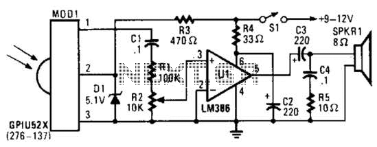
The infrared pulse-to-audio converter circuit operates by converting the infrared signals emitted by remote controls into audible sound. The heart of the circuit is the photo cell module, which is sensitive to infrared light. When an infrared signal is detected, the module generates a corresponding electrical signal. This signal is then fed into audio IC U1, which processes it to produce an audible output.
The circuit typically consists of a few key components: the photo cell module (P/N 276-137), audio IC U1, resistors, capacitors, and a power supply. The photo cell module is connected to the input of the audio IC, and it typically requires a power supply of around 5V to operate efficiently. Resistors may be used to adjust the sensitivity of the photo cell and to limit the current flowing into the audio IC, ensuring that it operates within its safe limits.
Capacitors can be included to filter out noise and stabilize the power supply to the audio IC, providing a cleaner output signal. The output from the audio IC can be connected to a small speaker or an audio output jack, allowing the user to hear the converted infrared signals as audible sounds.
This circuit can be particularly useful for technicians and hobbyists who need to diagnose issues with remote controls or for educational purposes to demonstrate the principles of infrared communication and audio signal processing. By providing audible feedback when an infrared signal is detected, users can easily identify the operation of remote controls and analyze their functionality. If your ear is good, you can use this IR-pulse-to-audio converter to troubleshoot infrared remote-controls. It is also a good project for detecting infrared-light sources. A photo cell module (Radio Shack P/N 276-137) detects IR radiation and drives audio IC Ul. This circuit is useful for troubleshooting IR remote controls. 🔗 External reference
Related Circuits
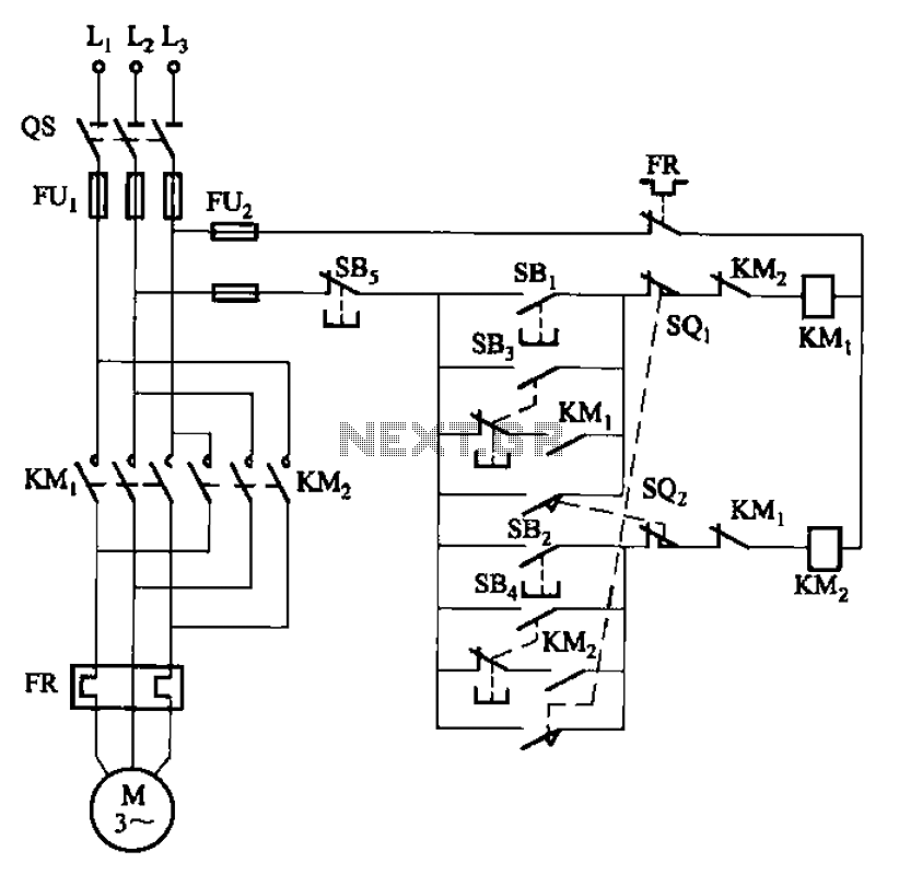
The circuit depicted in Figure 3-27 features a jog function that allows for precise adjustments of moving components. In the figure, SB3 and SB4 represent the forward jog and reverse jog buttons, respectively. When the SB3 button is pressed,...
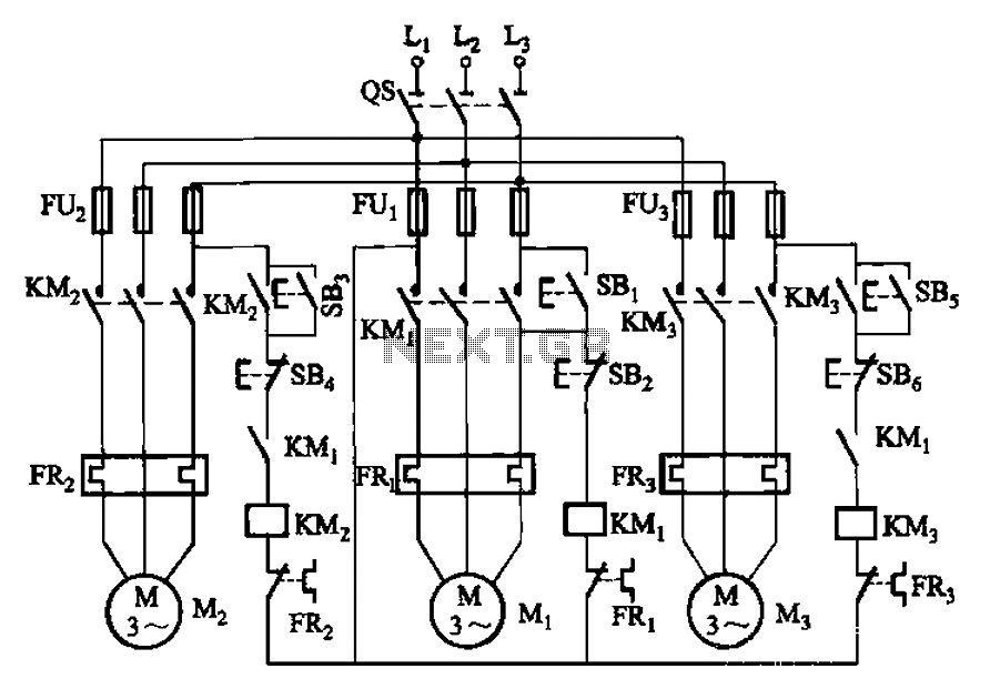
The circuit shown in Figure 3-89 illustrates a system where starting motor M1 allows motors M2 and M3 to initiate operation. Upon shutdown, motor Mz can be stopped first; however, once motor M1 is stopped (by pressing switch SB2),...
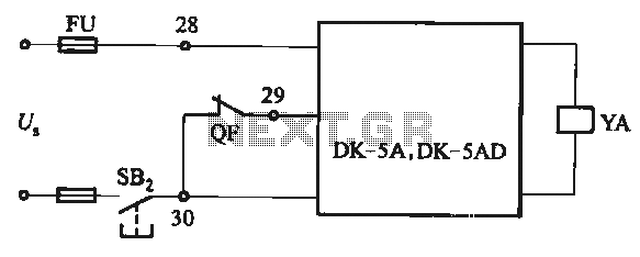
The DK-5A and DK-5AD AC power control circuit is illustrated in Figure 6-77. The figure includes a closing button (SBz) and a line (YA) connected to the closing electromagnet coil (U). This circuit is designed for the operation of...

The Tesla Coil will utilize a high voltage (HV) power source that outputs 9 kV at approximately 30 mA. The construction of the Tesla coil includes six glass bottles, table salt, oil, and aluminum foil for the capacitors. The...
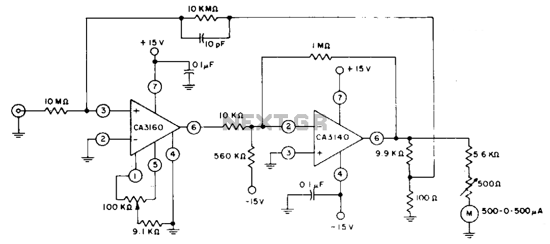
The circuit employs CA3160 and CA3140 BiMOS operational amplifiers to achieve a full-scale meter deflection of ±3 pA. The CA3140 functions as a 1T0 gain stage, supplying the necessary positive and negative output swing for the meter and the...
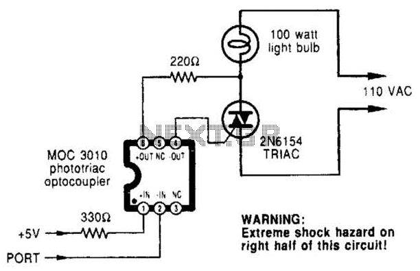
A microcomputer-to-triac interface utilizes a phototriac optoisolator to safely isolate logic signals, allowing direct control of high-power loads. This circuit can function as either an on/off switch or a proportional phase control, depending on the input waveforms and the...
Warning: include(partials/cookie-banner.php): Failed to open stream: Permission denied in /var/www/html/nextgr/view-circuit.php on line 713
Warning: include(): Failed opening 'partials/cookie-banner.php' for inclusion (include_path='.:/usr/share/php') in /var/www/html/nextgr/view-circuit.php on line 713