
FM Transmitter circuit diagram (50M) With 2N2222 Transistor

The FM transmitter circuit consists of several key components, primarily centered around the 2N2222 transistor, which serves as the main amplification element. The circuit is designed to operate within a voltage range of 3V, making it suitable for battery-powered applications.
The configuration typically includes a power supply connected to the collector of the transistor, while the base is driven by an audio input signal. This audio input can be sourced from various devices, such as microphones or audio players. A resistor is often placed between the base and the power supply to limit the current flowing into the base, ensuring the transistor operates within its safe limits.
The circuit utilizes a resonant LC circuit, which consists of an inductor and a capacitor, connected to the collector of the transistor. This LC circuit is crucial for determining the frequency of the transmitted signal. By adjusting the values of the inductor and capacitor, the operating frequency can be tuned to the desired FM band, usually between 88 MHz and 108 MHz.
A variable capacitor might be incorporated into the circuit to allow fine-tuning of the frequency, enhancing the transmitter's performance and enabling it to avoid interference with other signals. The output from the collector is then coupled to an antenna, which can be a simple wire, to radiate the FM signal over a distance of up to 50 meters, depending on the surrounding environment and the quality of the components used.
Overall, this FM transmitter circuit offers a straightforward and effective solution for low-power audio transmission, making it a popular choice for hobbyists and educational projects in the field of electronics.This is a FM transmitter circuit diagram. This circuit using 2N2222 Transistor so can be operated with 3V, and also can send signals up to 50m .. 🔗 External reference
Related Circuits
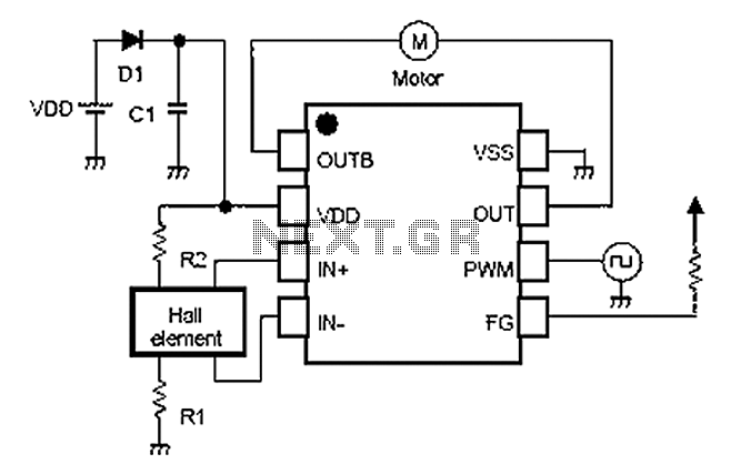
A simple single-phase brushless DC motor drive using the NJU7365 motor driver IC from New Japan Radio Co., Ltd. The NJU7365 is designed for single-phase motor applications and features built-in MOSFET motor drives, direct PWM input, FG output, and...

This transistor ignition circuit enhances vehicle starting and ensures smoother engine operation, especially at both high and low RPMs. It contributes to lower fuel consumption, reduced emissions, and decreased maintenance costs. The system promotes economical and electronic driving. The transistor...

The infrared remote-control tester employs a sensitive PN-type solar sensor directly connected to a Darlington amplifier composed of transistors Q1 and Q2. Biasing is achieved through resistor R1 and PI, a variable resistor that functions as a sensitivity control....

Both circuits can synchronize trapezoidal wave voltage, which is converted into intermittent small rectangular pulses. Its working principle involves periodic operation in synchronization with the grid frequency of the zero-volt switching voltage of the DC chopper. Due to the...
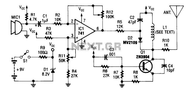
An operational amplifier integrated circuit (741) amplifies the audio signal from microphone MIC1, with resistor R12 adjusting its gain. The amplified audio is directed to the oscillator circuit, which includes transistor Q1 and associated components. D2 is a varactor...

This is a 100-watt transistor inverter circuit diagram that features a straightforward design. The circuit utilizes only transistors, eliminating the need for integrated circuits. It converts a 12V battery input into a 220V output with a 50Hz square wave...