
Boiler control circuit

The boiler control circuit operates through a carefully designed feedback mechanism that ensures the water temperature is maintained within desired limits. The thermistor outside the boiler door senses the ambient temperature, while the thermistor inside the boiler monitors the water temperature. Both thermistors are integral to the operation of the voltage dividers formed by their respective resistors.
When the external temperature is at or below 16 degrees Celsius, the values of resistors R1 and R2 are equal, establishing a baseline reference voltage for the comparator. This configuration allows the comparator to assess the temperature conditions effectively. Inside the boiler, when the temperature reaches 88 degrees Celsius, the equality of resistors R3 and R4 ensures that the voltage divider accurately reflects this critical threshold.
The comparator's output is pivotal in controlling the heating element. If the temperature exceeds 88 degrees Celsius, the comparator sends a high signal to the base of transistor VT. This action turns on the transistor, which completes the circuit to relay K. The activation of relay K interrupts the power supply to the heating element, effectively shutting down the heating process to prevent overheating.
This circuit design is crucial for maintaining safe and efficient operation of hot water heating systems. By continuously monitoring both external and internal temperatures, it ensures that the boiler operates within specified limits, enhancing both performance and safety. The use of thermistors for temperature sensing provides rapid response times and high accuracy, making this circuit a reliable choice for temperature control in heating applications. Boiler control circuit for controlling the temperature of water in the hot water heating system, often used comparator s comparison function to control the heating equipment. I ts control circuit is shown. Circuit, and thermistor products z hurricane form a voltage divider, dividing its value as a reference voltage applied to the U- end. Riz thermistor placed outside the boiler door. Rn and the resistance Rz is selected such that: when the external temperature is 16 when, RI2 and Rz of equal value.
Resistance R, and the thermistor R, t also form a voltage divider, dividing its value by the end of the U-ten. Thermistor R., Placed in a pot furnace inside t Rj- and the resistance Ri is selected according to the following conditions: when the boiler temperature is 88 when, Ru and Rt resistance should be equal.
To control the output of the comparator transistor VT. When the boiler temperature 88, the comparator output high, so VT turned on, causing the relay K to pull, turn off the heat source boiler.
Related Circuits
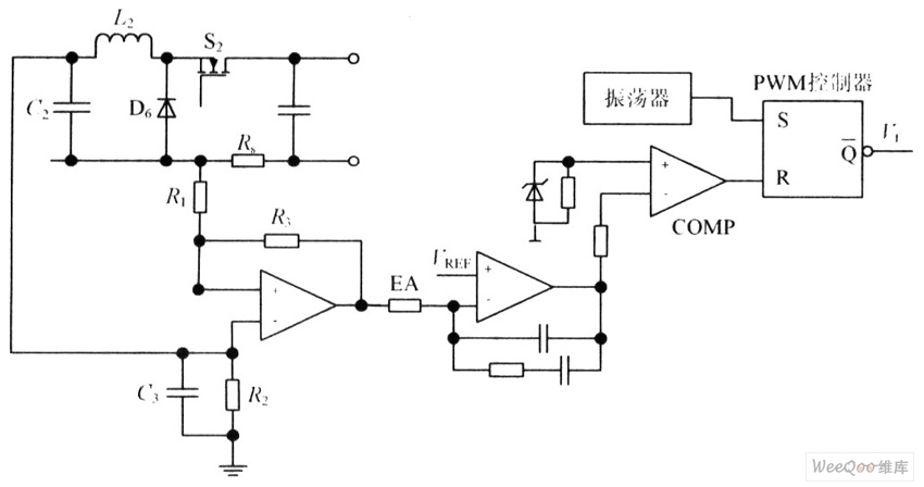
The circuit is capable of enhancing the system power factor to a value exceeding 0.99. It effectively reduces the waveform distortion of the input supply current, ensuring compliance with GB15144 standards, with a distortion index lower than level L....
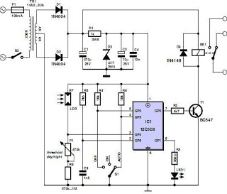
An effective domestic alarm system is most effective when it never activates, and the best way to achieve this is to create the illusion that the premises are occupied. Most burglaries are committed by petty thieves who seek simplicity...
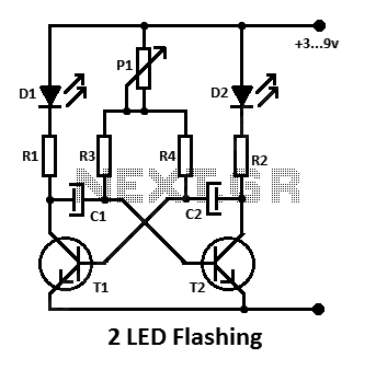
This is a simple flashing LED circuit featuring two LEDs and two NPN transistors. It demonstrates the behavior of transistors and capacitors, and it can be used in an oscillating configuration. The circuit consists of two NPN transistors, which function...
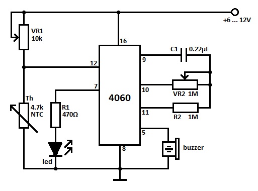
Two heat sensor circuits are presented. The first circuit is constructed using a 4060 integrated circuit (IC), while the second circuit is simpler and contains fewer components. This serves as a conceptual idea. The first heat sensor circuit utilizing the...
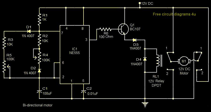
This circuit illustrates a bi-directional motor control circuit utilizing the NE555 integrated circuit (IC). Features include a 12V DC power supply, with the IC employed to control relay RL1. The bi-directional motor control circuit designed with the NE555 IC allows...
A circuit diagram of the T1 is a low-impedance output transformer, featuring a 5000-8 ohm resistor. The T1 low-impedance output transformer is designed to match the output of audio amplifiers to the impedance of loudspeakers, ensuring optimal power transfer and...