
MOSFET + Relay to Control a Motor
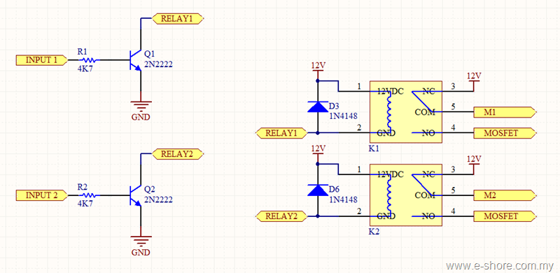
The connection of the relay to the motor should be noted, focusing on how the normally closed (NC), common (COM), and normally open (NO) terminals are connected to the motor terminals labeled M1 and M2. M1 and M2 connect to the COM of both relays, with the NC terminals connected to 12V and the NO terminals connected to the MOSFET. When the MOSFET is activated, it shorts the circuit to ground. For example, when K1 is OFF and K2 is ON, terminal 1 of the motor connects to 12V, and terminal 2 connects to ground, making the motor rotate clockwise. To reverse the direction to counter-clockwise, K1 must be ON and K2 OFF, connecting terminal 1 to ground and terminal 2 to 12V. If both relays are activated, both motor terminals are shorted to ground, resulting in an OFF or brake condition. The same occurs if both relays are deactivated.
The MOSFET component allows for speed control of the motor. The MOSFET driving circuit converts the PWM output from the microcontroller at 5V to a logic level of 12V. This circuit also inverts the PWM signal; when the microcontroller outputs 5V, the MOSFET driving circuit outputs 0V, and vice versa. This inversion can be managed in the microcontroller's programming, allowing for control of motor speed through PWM values, such as 0% for full speed, 50% for medium speed, and 100% for zero speed. Although it is possible to connect the PWM output directly to the gate of the IRF-Z48 N MOSFET, it is recommended to use additional transistors and resistors in the driving circuit to ensure optimal performance and prevent excessive internal resistance.
The overall design of this circuit effectively combines relay and MOSFET technologies to provide precise control over both the direction and speed of the motor, allowing for versatile applications in various electronic systems.Basically, the circuit is using relay (2 set of Relay for each Motor) to switch the direction of the motor and MOSFET (1 set of MOSFET for each Motor) to control the speed of the motor. I will divide the MOSFET + Relay circuit into 3 part for the description, hope that you can completely understand the schematic.
This part is basically about how m icrocontroller output ports drive Relays. I hope you understand about how a Relay operate or you can read more about Relay here. To control a Relay from microcontroller, you need to convert the digital output signal (normally 0V for logic 0 and 5V for logic 1) from microcontroller to the coil voltage of the Relay, in this case 12V. For your information the INPUT1 and INPUT2 pin should be connected to microcontroller. When the INPUT1 is logic 1, which is 5V, the Q1 will be turned ON, which also means RELAY1 pin will be shorted to GND.
What happen here is the K1 Relay will be turned ON. The K1 Relay coil, Port 1 is actually connected to 12V by default and now Port 2 is shorted to GND (due the Logic 1 output from INPUT1) which complete the circuit and turn ON the K1 Relay. However if the INPUT1 is logic 0, which will turn OFF the Q1 transistor, and RELAY1 pin will no longer shorted to GND.
This will break the K1 Relay coil circuit and the K1 Relay will be turned OFF. Looking at the Relay and Motor, try to focus on how the NC (Normally Close), COM (Common), and NO (Normally Open) is connected to the Motor terminal (labeled M1 and M2). M1 and M2 is basically connected to the COM of both relay, NC of both Relay is connected to 12V and NO of both Relay is connected to MOSFET, where it will be shorted to GND when the MOSFET is turned ON (this will be discuss on the next part).
Looking at the diagram above, when K1 is turned OFF and K2 is turned ON, terminal 1 of Motor is connected to 12V, and terminal 2 of Motor is connected to GND. Depend on your Motor, let say, if we apply +ve at terminal 1 and ve at terminal 2, the direction of the Motor will be Clockwise.
To make it Counter-Clockwise, all you have to do is turn ON K1 Relay and turn OFF K2 Relay. Now, when K1 Relay is turned ON and K2 Relay is turned OFF, terminal 1 of the motor is connected to GND and terminal 2 to the 12V, which will make the motor Counter-Clockwise. So, whichever Relay is turned ON, that side of Motor terminal will be connected to GND, and when Relay OFF, that side of Motor terminal will be connected to 12V.
What will happen if you turn ON both side of Relay The answer is simple, both terminal of Motor will be shorted to GND, and nothing will happen, the Motor is in OFF condition or BRAKE condition. The same thing happen if you turn OFF both side of Relay. From the Part 1, you`ve already able to control the direction of the Motor or turn OFF/BRAKE the motor, now, this MOSFET part will let you control the Speed of the Motor.
More information about MOSFET here. The circuitry above, is basically the MOSFET Driving Circuitry, that convert the PWM output from Microcontroller at logic 5V to Logic 12V. This MOSFET Driving Circuitry also invert the PWM signal from Microcontroller. In the other words, when the output from Microcontroller is 5V, the output of MOSFET Driving Circuitry will be 0V, and when the output from Microcontroller is 0V, the output of MOSFET Driving Circuitry will be 12V.
Don`t worry about the inverted signal from Microcontroller, you can re-invert the PWM output from Microcontroller in your programming to make it right. For example, let 0% PWM for full speed, 50% PWM for medium speed and 100% PWM for zero speed. This can be easily done in your coding. There is a reason that you need all those transistor and resistor simply to drive a MOSFET. For IRF-Z48 N MOSFET, you can actually connect the PWM output from microcontroller directly to the G of the MOSFET to drive it.
It will function correctly, but this will cause the internal resistance of the 🔗 External reference
Related Circuits
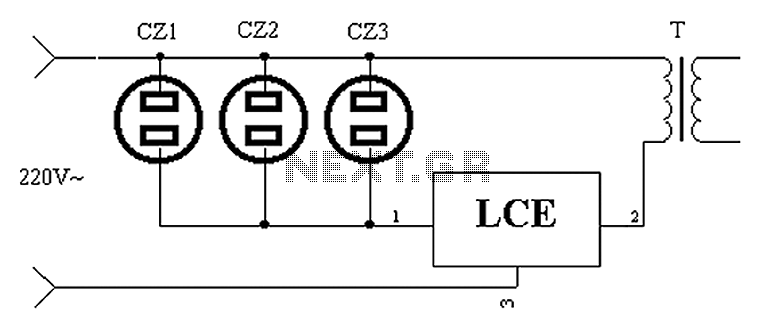
The application circuit operates as depicted below. It typically utilizes a shared TV antenna amplifier and an isolated power switch for the user. There are instances when the TV may not function, yet the antenna amplifier remains powered, leading...
This circuit operates at 73 MHz and is designed for controlling halogen lights through radio frequency remote control. The primary function is to toggle the power state of a halogen lamp. When the button on the remote control is...
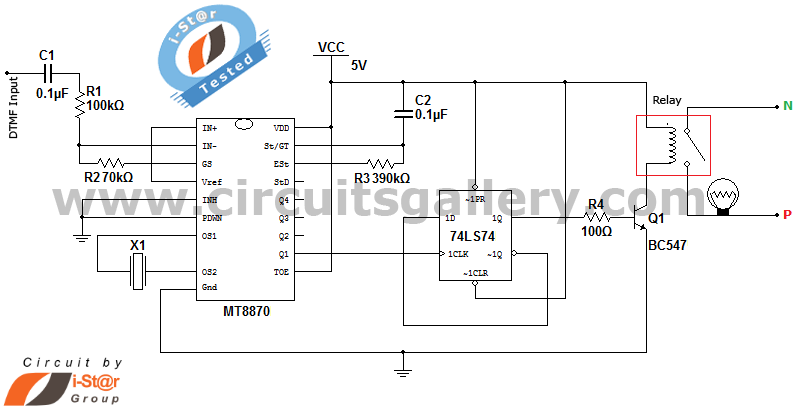
It is possible to control home and office electrical appliances using a mobile phone. This document presents a simple home automation electronic mini project circuit diagram designed for engineering students, allowing the control of electrical appliances without the use...
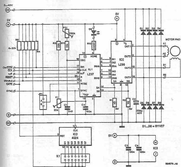
The L297 and L298 integrated circuits manufactured by SGS Thomson (ST) can be utilized to create a control circuit for a stepper motor, accommodating both two-phase bipolar and unipolar four-phase configurations, with a maximum current rating of 2 A...
The driver files are located in the Si570AVR-USB-Driver folder within the zip file. Extract these files into a new directory and connect the RX board's USB cable to a USB port. When prompted for the driver location, navigate to...
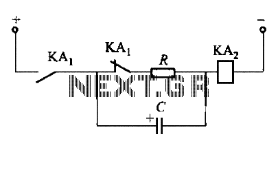
To fulfill the requirements of a control loop, it is often necessary to utilize an electromagnetic relay or a transistor relay to either accelerate or delay an action, thereby forming an acceleration or delay circuit. The circuit depicted in...