
Simple TV Remote Control Jammer

The circuit operates by generating a 38kHz modulated infrared signal, which is the standard frequency used by many remote controls. The key component, the infrared emitter diode, is responsible for producing this signal. The choice of diode is flexible, as various IR emitters can be employed, provided they are capable of operating at the required frequency.
The circuit design includes a current-limiting feature facilitated by two 1N4148 diodes, which are arranged in such a way that they stabilize the current flowing through the IR LED. This is crucial for maintaining consistent performance and preventing damage to the diode due to excessive current. The transistor in the circuit acts as a switch, allowing for the control of the IR LED's operation based on the circuit's design requirements.
In addition, the 5.6-ohm resistor plays a vital role in setting the appropriate current level through the IR emitter, ensuring that it does not exceed the 100mA threshold. This careful design consideration helps to maintain the longevity and reliability of the components involved.
Overall, this circuit serves a specific purpose of jamming the infrared signals from remote controls, thereby providing a unique solution for uninterrupted viewing. It is essential to ensure that such a device is used responsibly, as it may interfere with the normal operation of other devices in proximity.This circuit confuses the infra-red receiver in a TV. It produces a constant signal that interferes with the signal from a remote control and prevents the TV detecting a channel-change or any other command. This allows you to watch your own program without anyone changing the channel ! The circuit is adjusted to produce a 38kHz signal. The IR dio de is called an Infra-red transmitting Diode or IR emitter diode to distinguish it from a receiving diode, called an IR receiver or IR receiving diode. (A Photo diode is a receiving diode). There are so many IR emitters that we cannot put a generic number on the circuit to represent the type of diode.
Some types include: CY85G, LD271, CQY37N (45 ), INF3850, INF3880, INF3940 (30 ). The current through the IR LED is limited to 100mA by the inclusion of the two 1N4148 diodes, as these form a constant-current arrangement when combined with the transistor and 5R6 resistor. Link 🔗 External reference
Related Circuits
Jammer Store manufactures specialists share their unique experience with you. A detailed guide for skilled electronics fans on how to make your own jammer. The process of constructing a jammer involves a thorough understanding of radio frequency (RF) principles and...
This is a simple function generator built around a single 8038 waveform generator IC. The circuit is capable of producing sine, square, or triangle waves within a frequency range of 20Hz to 200kHz. The function generator circuit utilizes the 8038...
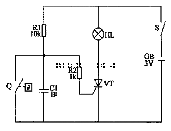
The automatic anti-frost crop controller circuit comprises an electric contact mercury thermometer (Q), a control circuit, ignition devices, and other components. The electric contact mercury thermometer features two platinum electrodes; one acts as a contact electrode inserted at the...
This circuit controls a load (in this case a DC brushless fan) based on a temperature compared with a setpoint. The transducer is a diode in the forward polarization regime. In fact, when forward biased, the forward voltage drop...
Infrared remote controls are using a 32-56 kHz modulated square wave for communication. These circuits are used to transmit a 1-4 kHz digital signal (OOK modulation) through infra light (this is the maximum attainable speed, 1000-4000 bits per sec)....
The use of pulse width modulation (PWM) is common for the use of controlling power to a particular electrical device. Motor speed control, LED contrast control, power supplies are some of the example usage of PWM. 18 series PIC...