
IR Remote Control Tester

The described circuit utilizes an SFH2030 photodiode, which is sensitive to infrared light, allowing it to effectively detect IR radiation from various sources. The photodiode generates a small current when exposed to infrared light, which is directly proportional to the intensity of the incoming IR radiation. This current is typically very low, necessitating amplification for practical measurement and visualization.
To amplify the signal from the photodiode, a CA3140 MOSFET operational amplifier is employed in a differential configuration. This configuration enhances the sensitivity of the circuit, allowing it to distinguish between varying levels of infrared intensity. The CA3140 is particularly suitable for this application due to its low input bias current and high input impedance, which minimizes the loading effect on the photodiode and ensures accurate signal amplification.
The output from the CA3140 is then used to drive an LED (LED1), which serves as a visual indicator of the presence and intensity of infrared radiation. The LED will illuminate when the photodiode detects IR light, providing a straightforward means of indicating the detection of infrared signals. The brightness of the LED can vary based on the intensity of the detected IR radiation, offering a qualitative measure of the IR light levels.
In summary, this circuit effectively combines a photodiode, a MOSFET op-amp, and an LED to create a simple yet effective IR intensity measurement system. It can be utilized in various applications, including remote control systems, IR communication, and other scenarios where infrared light detection is crucial. Proper calibration and adjustment of the gain settings of the op-amp may be required to optimize performance for specific applications.As I was developing my IR Extender Circuit, I needed to find a way of measuring the relative intensities of different Infra red light sources. This circuit is the result of my research. I have used a photodiode, SFH2030 as an infra red sensor. A MOSFET opamp, CA3140 is used in the differential mode to amplify the pulses of current from the photodiode.
LED1 is an ordinary coloured led which will light when IR radiation is being received. 🔗 External reference
Related Circuits
Figure 2-32 (a) illustrates the time control diagram for a motor operated by switch S1. When S1 is set to position 1, the power driver circuit supplies current to the motor, enabling it to run. When S1 is switched...

At the time, there was a desire to construct an ultimate continuity tester, leading to the creation of a wish list of required features. A genuine continuity tester is needed, as many multimeters and sounders react to resistances as...
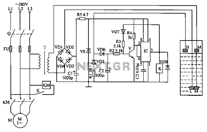
The circuit functions as a liquid level automatic controller, comprising a power circuit, a level detection circuit, and a control execution circuit. The power circuit includes a knife switch (Q), fuse (FU), power transformer (T), rectifier diodes (VD1 to...
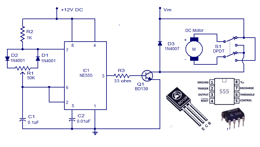
This weblog discusses electronic circuit schematics, PCB design, DIY kits, and electronic project diagrams. A simple DC motor controller circuit utilizing the NE555 timer is presented. Several DC motor speed control circuits are explored, with this being the first...
Microcontroller-based water tank filler circuit diagram. Differences between microprocessors and microcontrollers, parallel port interfacing projects using microcontrollers, applications of microcontrollers in real life, circuit diagram of AVR microcontroller trainer, 8086 microcontroller, microcontroller-based drip irrigation system circuit, design of pulse...
The power supply section is the important one. It should deliver constant output regulated power supply for successful working of the project. A 0-12V/500 mA transformer is used for this purpose. The primary of this transformer is connected in...