
Ultimate Continuity Tester Hides Many Tricks Up Its Sleeve

The ultimate continuity tester circuit is designed to provide accurate and rapid testing of low-resistance connections while avoiding common pitfalls associated with traditional multimeters. The non-inverting amplifier configuration ensures that the circuit is sensitive to low resistances, allowing it to detect connections that other testers may miss due to their higher resistance thresholds. The oscillation condition is crucial for the operational functionality of the tester, as it allows for audible feedback when a good connection is made.
The integration of a piezo buzzer provides a practical solution for indicating continuity without requiring expensive or bulky components. The protection mechanisms, including the fusible resistor and optional diodes, ensure that the circuit can withstand accidental connections to live circuits, enhancing safety and reliability in various testing environments. Additionally, the choice of using a low-voltage power source, such as a single AA battery, not only reduces costs but also simplifies the design, making it accessible for DIY enthusiasts and professionals alike.
Overall, this design exemplifies a balance between functionality, cost-effectiveness, and user convenience, making it an ideal tool for anyone needing a reliable continuity tester in their electronic toolkit. The ability to measure impedance, in addition to resistance, further enhances its utility, providing users with more comprehensive diagnostics for their electronic components and systems.At the time, I wanted to build The Ultimate Continuity Tester, and I established a wish list of all the features I required: A real continuity tester. Too many multimeters and sounders react at resistances as high as hundreds or even thousands of ohms, which makes them practically us
eless in many cases. Within a board or a system, there are always medium-conductivity paths everywhere, so they sound most of the time. A connector, a PCB track, or a wire, even a long one, has a resistance generally below 1. Having a threshold much higher than that generates false alarms. Speed. Many testers require a contact of tens of milliseconds or more, which makes the testing of large numbers of connections very frustrating.
It is impossible to swipe quickly across a large number of pins. Cheap to make and use. That meant a very small number of dirt-cheap components and a power consumption as frugal as possible from a cheap power source. This ruled out the usual 9-V battery, one of the least efficient and most expensive sources available.
No power switch. You invariably forget it`s on the afternoon preceding your holiday leave, and timers aren`t good enough. They tend to go off unnoticed just when you reach the wanted connection. At first sight, the circuit in Figure 1 doesn`t seem very impressive, but it fulfills all of these requirements, and then some.
It looks like some half-cooked multivibrator, but appearances can be deceptive. Q1 and Q2 form a two-stage, non-inverting amplifier, whose input and output are connected via C3 in order to cause oscillations. Each stage has its gain carefully defined: Q1 by the ratio of R4 to R1, and Q2 by the ratio of R2 to the sum of R8 and whatever sits between the test probes.
When the product of these gains exceeds unity, oscillation occurs. With the values shown, the oscillation condition is met when the contact under test is less than 5. Other values are possible by altering the R3/R4 ratio, or both resistors can be replaced by a trimpot, Aj1. To maximize the drive with the low supply voltage, the piezo-buzzer (BZ1) is connected between antiphase outputs of the oscillator.
The resulting sound isn`t very loud with a standard transducer, but it`s quite sufficient for a lab or office environment. R8, together with D1 and D2, protect the tester in case it`s accidentally connected to a live circuit.
It`s a 1-W, preferably fusible, resistor. For an extended and resettable protection, it can be substituted with a positive temperature coefficient resistor. If so, the resistor will be able to withstand a prolonged connection directly across the mains. Optional diodes D3 to D6 can be installed in parallel with the battery to ensure its protection. The battery can be a single standard or rechargeable AA cell, since the circuit operates from 1 to 1.
5 V. A power switch is unnecessary because the test terminals also act as a switch. The only quiescent current is caused by leakages in the components ”typically in the hundreds of nanoamperes range. When the terminals are shorted, the current rises to about 10 mA. So in normal operation, the battery will last for years, and it can be soldered in place. The buzzer can be any cheap, passive type. As noted, this circuit goes beyond the requirements of the ultimate continuity tester. For example, it not only checks the resistance, but also the modulus of the impedance presented to the test probes.
In some cases, this can make a big (and useful) difference. The secondary of a 50/60-Hz transformer will generally have a dc resistance below the 5- threshold, but its impedance is mainly inductive and higher than 5, so no oscillation will take place. There will simply be a light click at the instant the circuit is made, because BZ1 receives a pulse via R2 and R4.
This will always be the case when a galvanic contact is made between the probes. Thi 🔗 External reference
Related Circuits
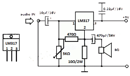
The LM317 integrated circuit (IC) is commonly recognized as a voltage regulator; however, it can also function as an audio amplifier. This low-power amplifier circuit designed with the LM317 provides a maximum output of approximately 1 watt. The LM317...
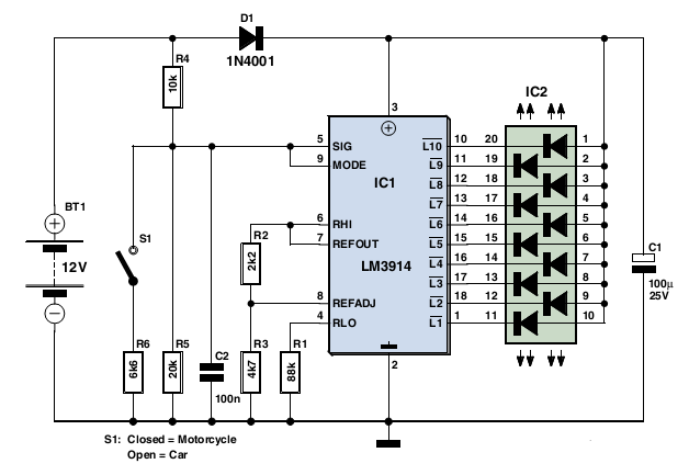
Typically, a charged lead-acid battery and a power inverter are utilized to ensure a well-organized holiday where family members can enjoy their electric and electronic devices. With rechargeable lead-acid batteries, it is often beneficial, if not essential, to determine...
Crystal Y1 generates a fundamental frequency clock signal of 14.31818 MHz. U31 is a Dual Voltage Controlled Oscillator (VCO) that produces a 14.31818 MHz clock signal, referred to as the color clock, at pin 10. The output frequency can...
The tester provides an audible indication of the logic level of the signal presented to its input. A logic high is indicated by a high tone, a logic low is indicated by a low tone, and oscillation is indicated...
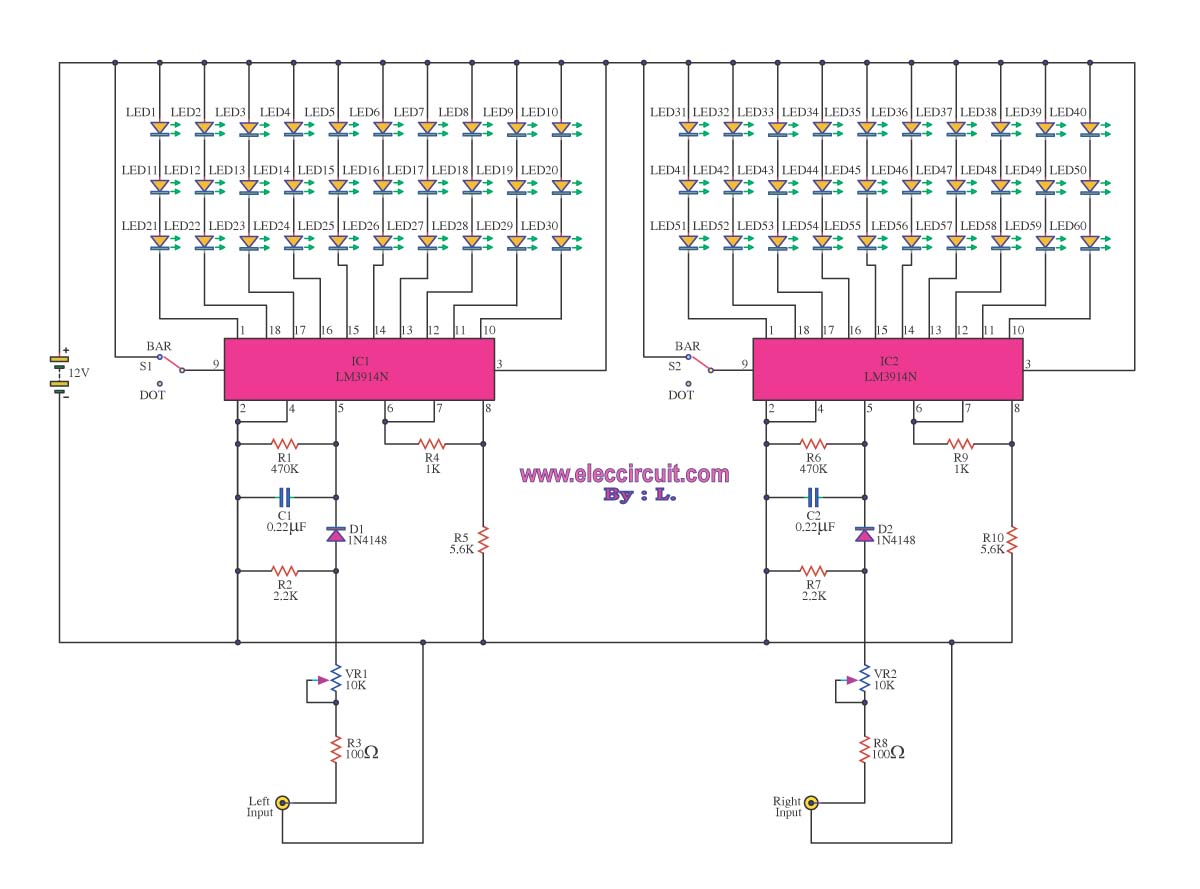
A VU meter is utilized to display the power level of audio signals and also serves as an aesthetic element. When purchasing a VU meter kit from an electronics store, options include assembling various parts independently or selecting a...
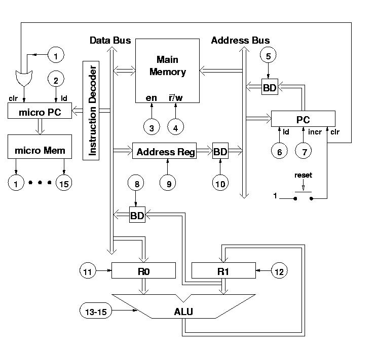
The diagram features a micro memory capable of storing up to 64 different addresses, each containing 15 bits, referred to as micro operations (MOPs). These MOPs govern all functions of the computer. Adjacent to the micro memory is the...