
IR Remote Control Tester Circuit
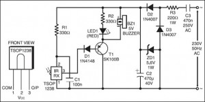
The IR Remote Control Tester Circuit is designed to verify the functionality of infrared remote controls. The core component of this circuit is the transistor T1, which plays a crucial role in detecting the infrared signals emitted by the remote control. When the remote is activated, it sends a series of infrared pulses, which are picked up by an infrared receiver diode in the circuit.
The circuit typically consists of the following components: an infrared receiver diode, a transistor (T1), resistors, a power supply, and a data output pin. The infrared receiver diode converts the incoming infrared signals into electrical signals. When the infrared pulse is detected, it causes the transistor T1 to conduct. This conduction occurs specifically during the negative pulse period of the infrared signal, allowing for the detection of the signal's presence.
The data output pin is used to provide a visual or audible indication of the detected signal. This could be connected to an LED, which lights up when the remote control is functioning correctly, or to a buzzer that sounds when a signal is received. The circuit can be powered by a standard DC power supply, ensuring that it operates effectively for testing purposes.
In summary, the IR Remote Control Tester Circuit serves as a practical tool for troubleshooting and verifying the operation of infrared remote controls by utilizing a simple yet effective design that highlights the key components and their functions.The following circuit shows about IR Remote Control Tester Circuit. Features: transistor T1 conducts during negative pulse period, data output pin . 🔗 External reference
Related Circuits
What is the recommended frequency for the Low Pass Filter used to control the contrast of an LCD? I want to adjust the contrast of an LCD using PWM. To effectively control the contrast of an LCD using Pulse Width...
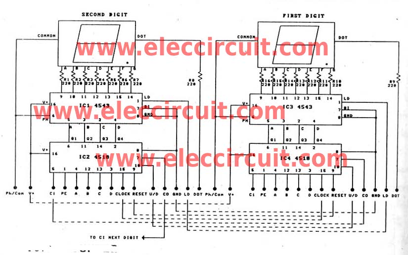
This is a versatile digital counter circuit that is cost-effective due to the basic components available in many electronic shops. The digital counter circuit is designed to count pulses and display the count on a digital readout, typically using a...
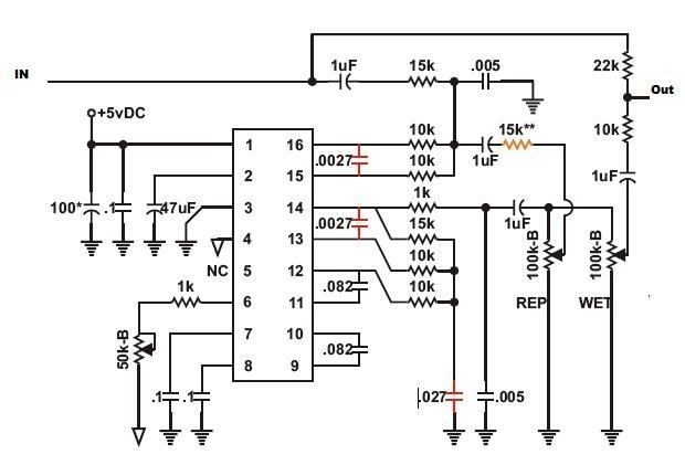
Recently, there has been a focus on Jeep repair due to an issue preventing the XJ from starting. However, during this time, progress has been made on initial modulation tests of the PT2399 circuit, resolving many bugs. The main...
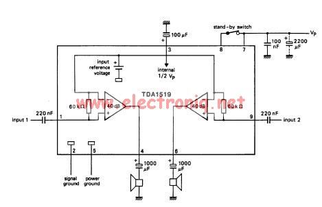
The TDA1519 circuit can deliver 2x6 watts output power. TDA1519 is an integrated class-B dual output amplifier in a 9-lead single in-line (SIL) plastic medium power package primarily developed for car radio applications. The TDA1519 is a robust integrated circuit...

This circuit provides protection for telephones, EPABX systems, telephone modems, and similar devices against lightning discharges and line voltage spikes. It incorporates a safety capacitor and gas discharge components. The circuit employs a safety capacitor to filter out high-frequency noise...
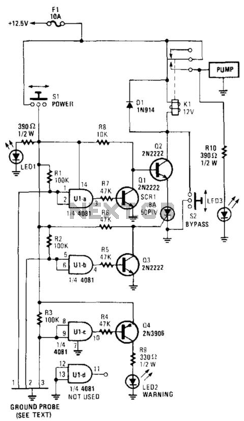
This circuit powers a water pump when the water reaches a predetermined level and turns off when the water recedes to another predetermined point. Gates U1A through U1C have their two inputs tied together and serve as probes placed...
Warning: include(partials/cookie-banner.php): Failed to open stream: Permission denied in /var/www/html/nextgr/view-circuit.php on line 713
Warning: include(): Failed opening 'partials/cookie-banner.php' for inclusion (include_path='.:/usr/share/php') in /var/www/html/nextgr/view-circuit.php on line 713