
Water-Level Control
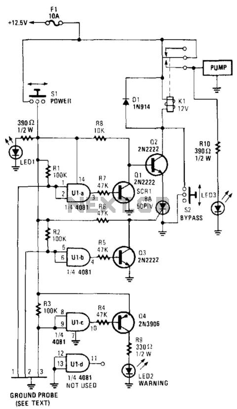
This circuit operates as an automated water level control system, utilizing three probes positioned at different heights to monitor the water level. The configuration of gates U1A, U1B, and U1C as voltage probes allows for precise level detection. The use of a 100-KOhm resistor ensures that the inputs to the gates remain high until the water level engages the probes, creating a reliable and responsive system.
When the water level rises to probe 1, the corresponding low signal activates a sequence of events. Q1's deactivation and Q2's activation place the circuit into standby, which is critical for ensuring that the pump does not activate prematurely. The activation of Q3 upon reaching probe 2 is crucial, as it allows SCR1 to latch, ensuring that once the pump is activated, it remains operational until the water level drops below probe 1. This latching mechanism is vital for maintaining pump operation during fluctuating water levels.
The inclusion of probe 3 as a warning system enhances the functionality of the circuit by providing a visual indicator (LED2) when the pump fails to operate, thereby enabling timely maintenance or intervention. The manual override switch S2 offers flexibility for users to control the system manually when necessary, while the status indicators (LED1 and LED3) provide clear visual feedback regarding the operational state of the sensor and pump circuits.
Overall, this water level control circuit is a robust solution for automating water pump operations, ensuring efficient management of water levels with added safety and operational features. This circuit will power up a water pump when the water reaches a predetermined level. Then it turns itself off when the water recedes to another predetermined point. Gates U1A through U1C each have their two inputs tied together, and serve as probes. The probes are then placed at various levels to trigger a particular function at a predetermined time. The ground side of the circuit is placed below the minimum water level. The inputs to each gate are tied high through a 100-KOhmhm resistor connected to the + 12.5-V bus. As the water level slowly rises to probe 1, the input to Ul A is pulled low by the conduction of current through the water to the ground probe.
That turns Ql off and Q2 on. With Q2 turned on, the circuit is placed in the standby mode, ready to activate the pump when conditions are right. Probe 2 is placed at the maximum water level. If the water level reaches probe 2, the input of U1B is brought low, turning Q3 on, which, in turn, causes current to be applied to the gate of SCR1, turning it on.
The circuit through Kl, Q2, and SCR1 is now complete to ground, and the water pump is now turned on, which causes the water level to recede. When the water level falls below probe 2, U1B goes back to logic high. However, because of the latching nature of SCR1, the pump continues to run until the water level falls below probe 1.
At that point, the ground circuit opens and de-energizes Kl, which turns the pump off. The pump will not turn on again until the water level again rises above probe 2. Probe 3 was added as a warning. If the water level reaches probe 3, LED2 indicates that the pump is not working. Switch S2 is a manual override and SI powers the sensing circuit. LED3 indicates that power has been applied to the pump. LED1 indicates that power has been applied to the sensor. 🔗 External reference
Related Circuits
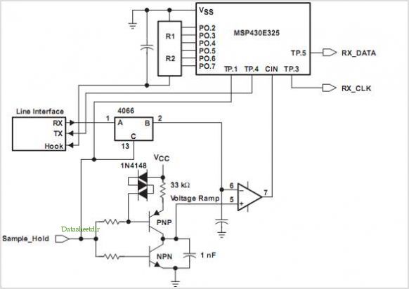
The FX919A is a CMOS integrated circuit that includes all necessary baseband signal processing and Medium Access Control (MAC) protocol functions for a high-performance 4-level Frequency Shift Keying (FSK) Wireless Packet Data Modem. It interfaces with the modem host...
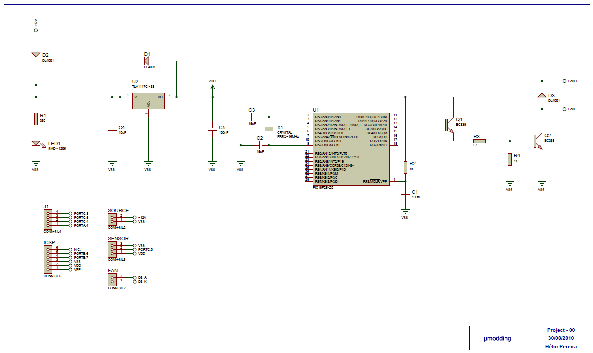
This project is based on a PIC18F25K20, with the purpose of controlling a fan with PWM (Pulse Width Modulation). It offers variable speed control, low acoustic noise, reliability, long lifetime, low power consumption, and protection features. The MCU gets...
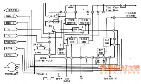
MN67641VDGF IC pin functions and data. MN67461VDGF IC's internal circuit block diagram and its typical application circuit. MN67461VDGF is a servo control IC produced by Panasonic, widely used in video cameras, such as the Panasonic NV-M8000 camera. Features: The...
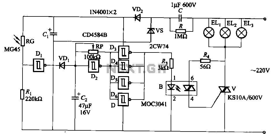
The circuit utilizes a CD4584B six Schmitt trigger integrated circuit (IC) with components Di and Ri forming a photometric circuit. D2, along with RP and C2, comprises an adjustable frequency ultra-low frequency oscillation device, where RP serves as an...

This 555 timer circuit is a remote control jammer device that is useful for blocking the use of remote controls, particularly when children frequently change channels or settings. The 555 timer is a versatile integrated circuit that can be configured...
The lack of compensation facilitates the processes of development and testing. The figure of 6 billion frequently appears as the estimated number of cell phones in use globally. Published estimates indicate an average. The discussion of compensation in electronic circuits...
Warning: include(partials/cookie-banner.php): Failed to open stream: Permission denied in /var/www/html/nextgr/view-circuit.php on line 713
Warning: include(): Failed opening 'partials/cookie-banner.php' for inclusion (include_path='.:/usr/share/php') in /var/www/html/nextgr/view-circuit.php on line 713