
IrDA Interface

The infrared data transmission module designed for integration with modern motherboards serves as a compact solution for enabling IrDA communication. Utilizing the TFDU6102 transceiver IC, the module achieves data rates up to 4 Mbit/s and supports various communication modes including FIR and HP-SIR. The design focuses on minimizing the number of required external components, as the transceiver integrates essential functions such as a photodiode and an infrared emitter, along with necessary CMOS control logic.
The module's compact PCB dimensions of 20 mm x 20 mm allow for versatile placement options within the device's enclosure, such as behind a drive bay cover. The choice of surface-mount device (SMD) components facilitates a compact layout, which is crucial for modern electronics where space is often at a premium. The upright version of the TFDU6102 is specifically selected for this application to optimize the assembly process and ensure compatibility with the motherboard's header.
Connections to the motherboard are made via a five-way flat cable, ensuring a reliable interface for data transmission. It is essential that the pin assignments for header X1 are accurately matched to the corresponding connector on the motherboard to ensure proper functionality. Following the physical installation of the module, BIOS settings must be configured to enable the UART for IrDA operation. This step is critical for the operating system to recognize the new hardware and facilitate driver installation.
The module's versatility extends beyond desktop applications; it is suitable for use in a wide range of devices including portable electronics, printers, and cameras, making it a valuable addition to any system requiring infrared communication capabilities. Additionally, the availability of free software that utilizes the IrDA interface enhances the module's utility, providing users with a range of applications for data transfer and remote control functionalities.Many modern motherboards are equipped with an infrared data interface compliant with the IrDA standard, but this interface not very often used. However, it is not difficult to build a data transmission module and connect it to the corresponding header.
As can readily be seen from the schematic diagram, this doesn`t exactly involve a large array of ICs. This is because transceiver ICs are available for the IrDA standard, so only a few passive components have to be added to obtain an operational circuit. The author has successfully built this circuit many times using the TFDU5102 from Vishay Semiconductors (formerly Telefunken).
If this IrDA transceiver is no longer available (it has been officially discontinued), the largely pin- and function-compatible TFDU6102 can be used without any problems. This IC is faster and meets the latest IrDA specification. The TFDU6102 low-power receiver IC supports IrDA at data rates up to 4 Mbit/s (FIR), HP-SIR, Sharp ASK, and carrier-based remote control modes up to 2 MHz.
The IC contains a photo-diode, an infrared emitter and CMOS control logic. The IC also has internal protection against electromagnetic immissions and emissions, so no external screening is necessary. The IC works with a supply voltage of 2. 7 5. 5 V, so it is suitable for use in desktop PCs, notebooks, palmtops, and PDAs. It is also used in digital still and video cameras, printers, fax machines, copiers, projectors, and many other types of equipment.
The author has designed a printed circuit board for the IrDA module that is only 20 G— 20 mm square. Of course, this means that all of the components are SMD types. The TFDU6102 in the babyface` package is available in upright and‚at versions. Here the upright version (suffix TR3`) is used. Thanks to its small size, the assembled circuit board can easily be placed behind a drive bay cover or the like. It is connected to the motherboard by ave-way‚at cable. The pin assignments for header X1 must match the mating connector on the motherboard. After you have fitted the module, you may have to edit the BIOS settings to activate the UART for IrDA operation.
These settings enable the (Windows) operating system to boot the new device and automatically install it. You may have to brie‚y insert the Windows CD to modify the settings. There is an abundance of free programs on the Internet that use the IrDA interface. 🔗 External reference
Related Circuits
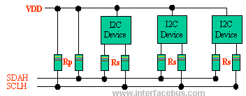
The I2C bus employs a bi-directional Serial Clock Line (SCL) and Serial Data Line (SDA). Both the SCL and SDA lines are pulled high using a pull-up resistor (Rp). An optional resistor (Rs) is utilized for ESD protection in...

Several possible interface circuits are presented for use with a remote-control transmitter. The circuit labeled A demonstrates a typical FM stereo MUX decoder with a load connected directly to the open-collector output of a TA7343 PLL. The circuit labeled...
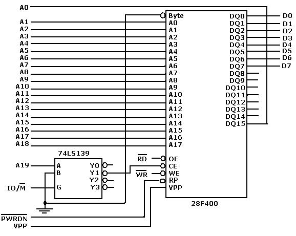
Flash memory, also known as flash RAM, is a type of non-volatile semiconductor memory device that retains stored data even when not powered. It is an enhanced version of electrically erasable programmable read-only memory (EEPROM). The primary distinction between...
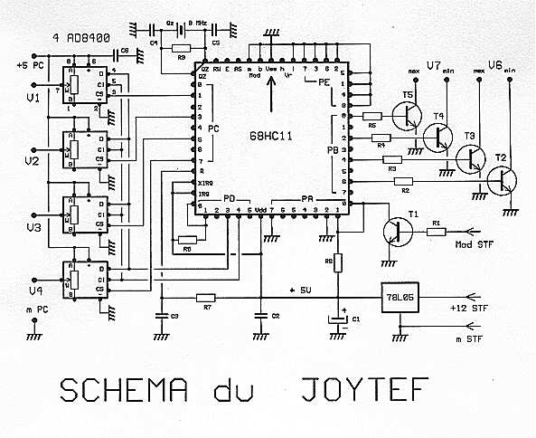
Using the software during flight simulation models of planes: REAL-FLIGHT, we first chose a housing of any transmitter empty direct connection potentiometers innings. However, this is not good because, first races of the potentiometers are only 90 degrees, which...
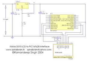
This project demonstrates the interfacing and operation of the Nokia 3310 LCD using the PIC16F628 microcontroller. The programming is executed in Hi-Tech C, with the character table incorporated within the source code. The Nokia LCD features a resolution of...
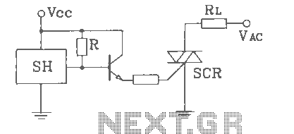
SH Hall opened with a double silicon output interface circuit The SH Hall sensor circuit is designed to provide a dual silicon output interface, which enables enhanced signal processing capabilities. This circuit typically integrates a Hall effect sensor that detects...