
Isolated Voltage Sensor With IN4148 IC
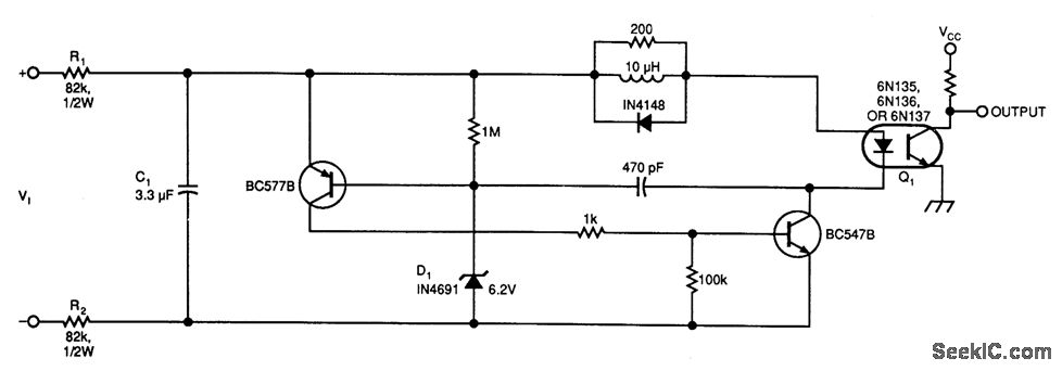
The voltage-controlled oscillator (VCO) circuit operates by generating a periodic waveform whose frequency is determined by an input control voltage. The primary components of this VCO may include a voltage-controlled capacitor, a resistor network, and an operational amplifier configured as an integrator. The output of the VCO typically provides a square wave or triangular wave signal, which can be utilized in various applications such as signal modulation, frequency synthesis, or as a clock source in digital circuits.
The inclusion of an optoisolator serves to electrically isolate the VCO from the instrumentation, ensuring that any high voltages or noise present in the VCO circuit do not affect the sensitive measurement equipment. The optoisolator consists of an LED and a phototransistor; when the LED is activated by the VCO output, it emits light that triggers the phototransistor, allowing for a corresponding signal to be transmitted to the instrumentation side without direct electrical connection.
In this configuration, the VCO can be tuned by varying the control voltage, which adjusts the capacitance and resistance values, ultimately changing the frequency of the output signal. This design is particularly advantageous in scenarios where electrical isolation is crucial for safety and signal integrity, such as in industrial automation, communication systems, and electronic testing environments.This circuit bellow shows a simple voltage-controlled oscillator (VCO), coupled to your instrumentation by an optoisolator, the function for .. 🔗 External reference
Related Circuits
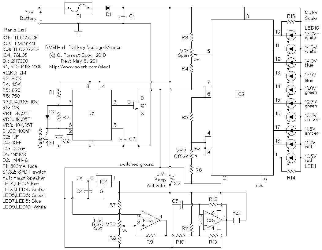
This circuit provides an audible and visual low voltage warning for 12V battery powered devices. When the battery voltage is above the set point (typically 11V), the circuit is idle. If the battery voltage should fall below the set...
This schematic diagram illustrates a water level sensor, detector, and monitor circuit. An alarm is also integrated into this circuit. It is designed to detect any fluid with a resistance below 900K ohms. The water level sensor circuit typically employs conductive...
The following circuit illustrates a PIR Sensor Timer Circuit Diagram. Features include a simple design, enhanced accuracy, and efficiency. Components involved are a diode, among others. The PIR (Passive Infrared) Sensor Timer Circuit is designed to detect motion through infrared...
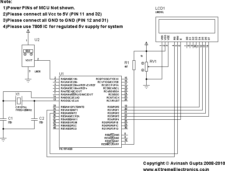
In the present day, a wide variety of sensors are available to measure almost anything. This tutorial will explore the fascinating world of sensors, starting with a very simple analog temperature sensor, the LM35. The process of interfacing it...

A biaxial magnetic field sensor application circuit is illustrated in the figure. This circuit utilizes a biaxial magnetic sensor HMC1002 along with two AMP04 operational amplifiers (A1, A2) to measure the magnetic field in both the X-axis and Y-axis...
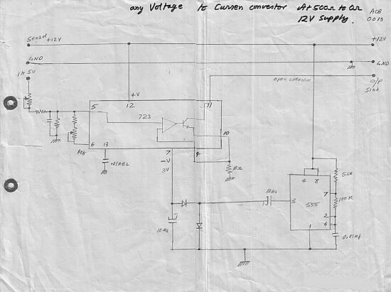
This circuit converts a voltage control output from a process controller into a current control signal, suitable for applications such as AC drives or valves requiring a current control signal. It operates as a three-wire voltage-to-current loop converter. The...